Catalyst layer

a catalyst layer and electrode layer technology, applied in the field of catalyst layers, can solve the problems of high electrochemical potential, damage to the catalyst layer/electrode structure, detrimental to the performance of fuel cell components, etc., and achieve the effects of stable catalyst layer, low platinum loading, and high performan

Active Publication Date: 2021-10-26
JOHNSON MATTHEY HYDROGEN TECH LTD
View PDF22 Cites 0 Cited by
  • Summary
  • Abstract
  • Description
  • Claims
  • Application Information

AI Technical Summary

Benefits of technology

[0015]For fuel cells to become commercially viable, particularly for automotive use, it is necessary to provide a high performance and stable catalyst layer, but with a low platinum loading. Using an unsupported “Pt black” catalyst in the catalyst layer compared to a carbon supported platinum catalyst can provide a more durable catalyst layer by avoiding the problems associated with carbon corrosion that occurs as a result of the high potentials caused by incidences of cell reversal and start-up shut-down. However, the present inventors have found that to produce a Pt black catalyst layer with the required structure for satisfactory operation and with sufficient uniformity and continuity of coating of the catalyst layer on the substrate, the platinum loading required is much higher than the requirements for commercialisation of many fuel cell applications, and in particular for automotive applications. The present inventors have surprisingly found that incorporation of a highly electrically conductive and corrosion resistant carbonaceous material into the catalyst layer enables suitable catalyst layer structures to be produced, that are also of excellent uniformity and continuity and that have a platinum loading in the catalyst layer consistent with automotive requirements.

Problems solved by technology

High electrochemical potentials can occur in a number of real-life operational situations and in certain circumstances can cause damage to the catalyst layer / electrode structure, primarily due to corrosion of any carbon present in the layer, such as the support material for the catalyst.
In addition to the loss of power associated with one or more cells going into voltage reversal, undesirable electrochemical reactions may occur which detrimentally affect fuel cell components.(ii) Start-up shut-down: for many fuel cells it is not practical or economic to provide purging of hydrogen from the anode gas space with an inert gas such as nitrogen during shut down.
Under these circumstances an internal cell can exist, which leads to high potentials on the cathode.

Method used


Image

  • Catalyst layer
  • Catalyst layer

Examples


example 1

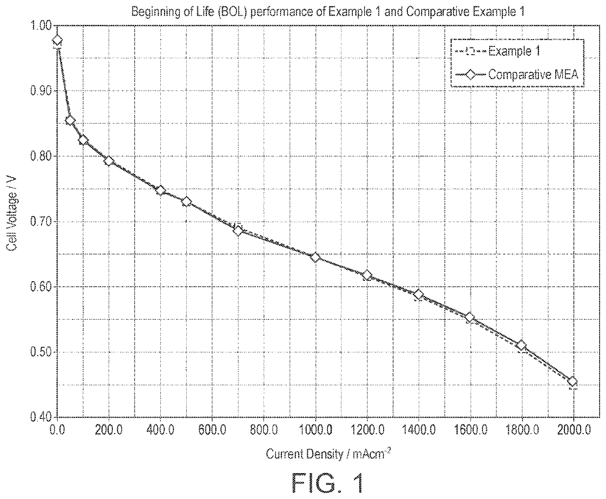
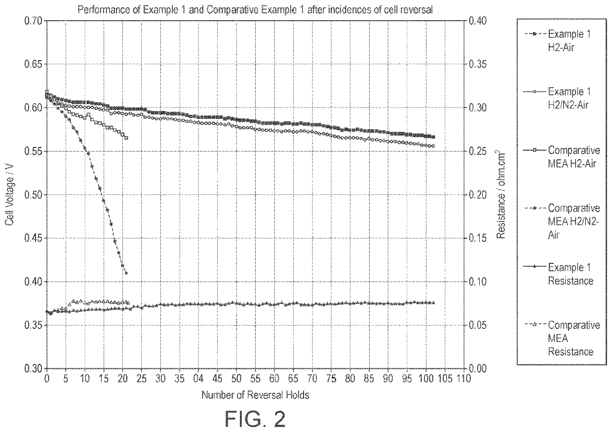
[0088]An anode catalyst ink was prepared by mixing an unsupported platinum black catalyst (Johnson Matthey, HiSPEC 1000) with an aqueous dispersion of a perfluorosulphonic acid ionomer of equivalent weight 790 (Solvay Plastics, D79-25BS Dispersion) at a level of 16 wt % ionomer relative to the weight of platinum. The aqueous solution had a total solids content of 45%. The platinum black powder was added to the diluted ionomer dispersion at 65° C. with stirring. This dispersion was mixed using a high shear mixer to ensure the components were evenly dispersed before processing through a bead mill, to reduce the particle size of the Pt catalyst. An oxygen evolution catalyst (Johnson Matthey, IrO2 / TaO2 prepared as described in WO2011 / 021034) was added to the diluted ink to achieve a ratio by weight of 1.0:1.26 Pt:IrO2 / TaO2. The catalyst was gently stirred into the ink to ensure even distribution. After processing the ink was diluted with neat propan-1-ol to 35% total solids (propanol co...


PUM

PropertyMeasurementUnit
thicknessaaaaaaaaaa
thicknessaaaaaaaaaa
particle sizeaaaaaaaaaa

Abstract

A catalyst layer including: (i) a platinum-containing electrocatalyst; (ii) an oxygen evolution reaction electrocatalyst; (iii) one or more carbonaceous materials selected from the group consisting of graphite, nanofibres, nanotubes, nanographene platelets and low surface area, heat-treated carbon blacks wherein the one or more carbonaceous materials do not support the platinum-containing electrocatalyst; and (iv) a proton-conducting polymer and its use in an electrochemical device are disclosed.

Description

FIELD OF THE INVENTION[0001]The present invention relates to a catalyst layer, which shows tolerance to high voltage situations, such as cell reversal and start-up shut-down incidences that occur in fuel cells. The invention also relates to electrodes, catalyst-coated membranes and membrane electrode assemblies comprising the catalyst layer.BACKGROUND OF THE INVENTION[0002]A fuel cell is an electrochemical cell comprising two electrodes separated by an electrolyte. A fuel, e.g. hydrogen, an alcohol such as methanol or ethanol, or formic acid, is supplied to the anode and an oxidant, e.g. oxygen or air, is supplied to the cathode. Electrochemical reactions occur at the electrodes, and the chemical energy of the fuel and the oxidant is converted to electrical energy and heat. Electrocatalysts are used to promote the electrochemical oxidation of the fuel at the anode and the electrochemical reduction of oxygen at the cathode.[0003]Fuel cells are usually classified according to the natu...

Claims


Application Information

Patent Timeline
Patent Type & Authority Patents(United States)
IPC IPC(8): H01M4/92H01M4/88H01M4/96C25B9/23C25B11/091C25B11/095H01M8/1018
CPCH01M4/928C25B9/23C25B11/091C25B11/095H01M4/8814H01M4/8828H01M4/96H01M2008/1095Y02E60/50
Inventor BURTON, SARAH LOUISEDICKINSON, ANGUS JOHNO'SULLIVAN, JULIE
Owner JOHNSON MATTHEY HYDROGEN TECH LTD
Why Eureka
Try Eureka