Microparticles

a technology of microparticles and microparticles, applied in the field of microparticles, can solve the problems of poor encapsulation efficiency of "too small" spheres, poor control of etc., and achieve the effect of controlling drug release rate and sphere size and shell thickness

Inactive Publication Date: 2002-05-09
THE BOARD OF TRUSTEES OF THE UNIV OF ILLINOIS
View PDF0 Cites 149 Cited by
  • Summary
  • Abstract
  • Description
  • Claims
  • Application Information

AI Technical Summary

Benefits of technology

0107] Fabrication of composite core/shell microparticles. With the multi-nozzle methodology, composite particles of two or more different materials can be fabricated. Core/shell micro-particles for drug delivery have been produced previously, but only with immiscible core and shell phases. In addition, control of sphere size and shell thickness was poor. Fine control of shell thickness and sphere diameter are possible. The two phases could comprise: a gas core within a polymer shell; a drug-containing aqueous core within a polymer shell (the shell could also encapsulate a second or the same compound); a polymer core encapsulating a drug compound within a polymer shell (of the same or different material) encapsulating a second or the same compound. Such particles could produce novel and useful drug-release rate profiles.
0108] Control of drug release rate from microshells. Encapsulation of water-soluble compounds in hydrophobic polymer microspheres typically requires a double-emulsion method in which a drug/aqueous phase is emuls...

Problems solved by technology

Unlike traditional small-molecule drugs, however, proteins and peptides generally cannot be administered orally; injection or infusion is most often required.
Sphere size and size distribution are reproducible but often poorly controllable.
Spheres that are "too small" exhibit poor encapsulation efficiency, may migrate from the site of injection, and may exhibit undesirably rapid release of their payload.
Spheres that are "too large" may not easily pass through a syringe needle.
Thus, the typically polydisperse spheres generated by conventional fabrication techniques must be filtered or sieved to isolate particles within the desired size range, and the polymer and drug composing spheres outside that range are wasted.
The success of the latter studies was limited by the relatively broad microsphere size distributions.
However, none of these methods was successful in generating particles in a size range appropriate for drug delivery (.about.1-100 .mu.m) while maintaining narrow size distributions.
In addition, these previous methods appear to be difficult to scale-up for commercial applications.
This in turn indicates pract...

Method used


Image

  • Microparticles
  • Microparticles
  • Microparticles

Examples


example 1

Fabrication of Uniform Solid PLGA Microspheres

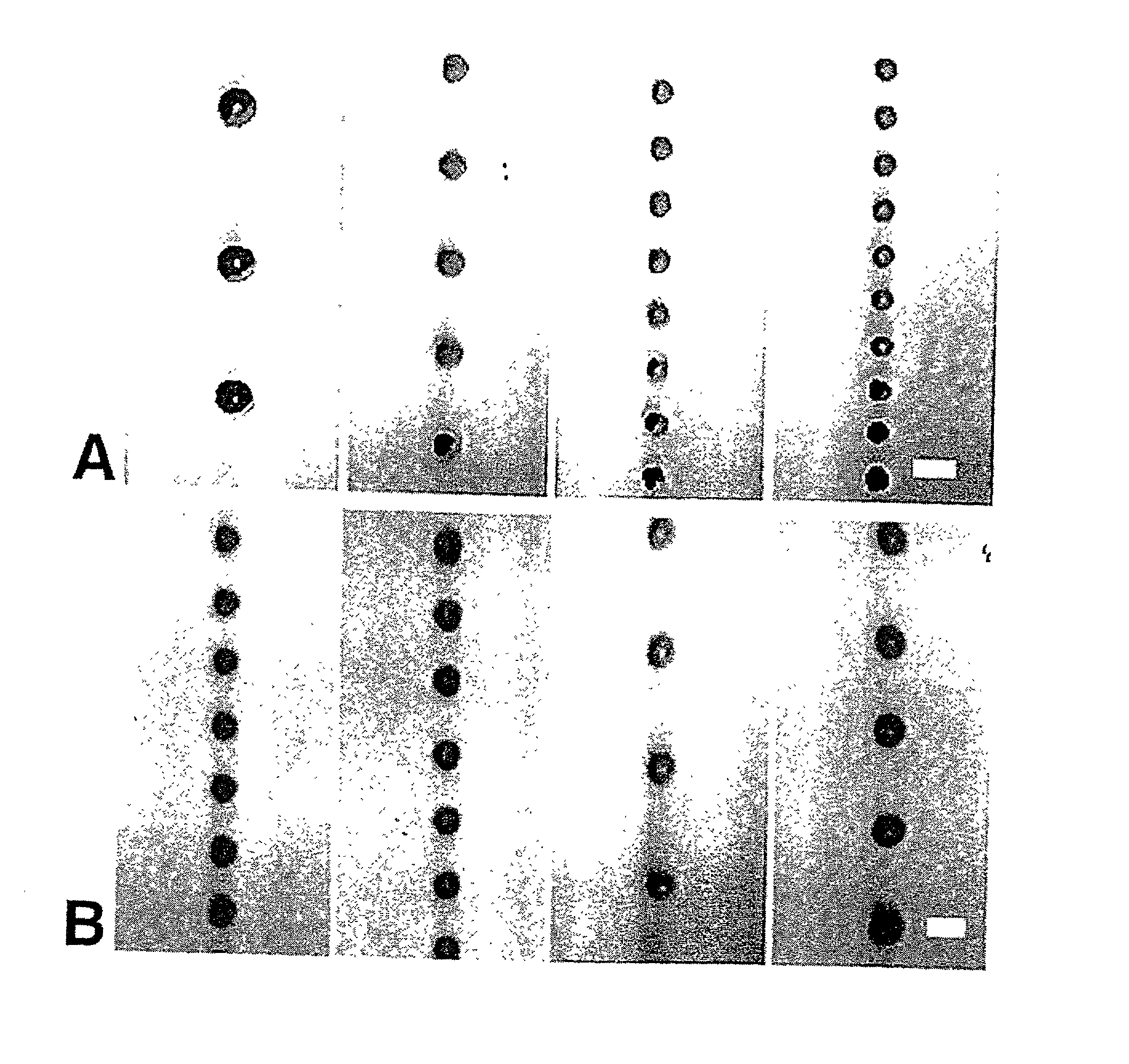
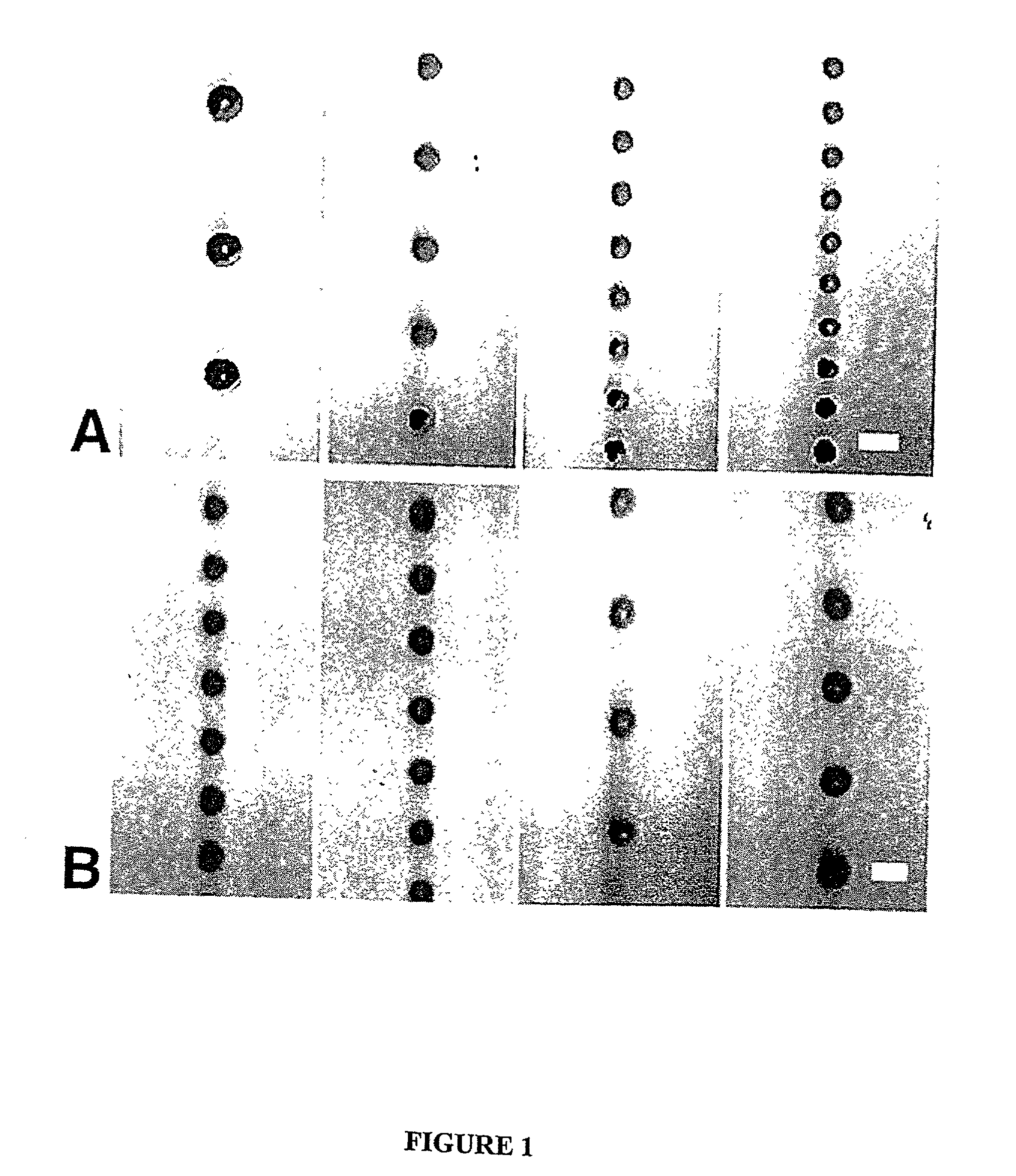
[0130] PLGA was dissolved in ethyl acetate (50 mg / ml) and the solution was pumped through a 60-.mu.m orifice at varying flow rates from 2-3 mil / min. Simultaneously, the acoustic excitation frequency was varied from 14 to 70 kHz. The free-falling spheres were illuminated with a strobe lamp and the images were captured on videotape using a 10.times.microscope objective and a CCD camera. As shown in FIG. 1, spheres that are homogenous in size from 65 to 120 .mu.m have been fabricated (note that the minimum sphere size is only slightly larger than the orifice diameter). The sphere size increased with increasing polymer solution flow rate and decreasing ultrasound frequency.

[0131] Uniform spheres have been formed over a wide range, from 15-500 .mu.m, using the same technique, but varying the orifice diameter, polymer solution flow rates and ultrasound frequency. The microspheres were hardened by solvent extraction / evaporation in an aqueous so...

example 2

Preparing PLGA of Smaller Sphere Size

[0133] The minimum sphere diameter obtainable with this basic technique is governed by the size of the nozzle. Decreasing the orifice size beyond .about.30 .mu.m is problematic for several reasons. First, reproducible fabrication of the nozzles, by pulling capillaries for example, is increasingly difficult as the size decreases. Second, very small nozzles are easily clogged by aggregated polymer or foreign dust particles, and careful washing of all equipment and filtering of solutions is required. These are simply technical problems that could be overcome with careful engineering of the system. A confounding problem, however, is that passing the viscous polymer solutions through the small orifices becomes increasingly difficult and generates larger shear forces as the orifice diameter is decreased. Thus, the electrohydrodynamic spraying technique has been explored to produce microspheres less than about 30 .mu.m in diameter.

[0134] The electrohydr...

example 3

Encapsulation of Drugs

[0136] Finally, the ability to encapsulate drugs within the polymer microspheres using a model compound, rhodamine B has been demonstrated. The rhodamine B, in its free base form, was dissolved in PLGA / ethyl acetate solutions at theoretical loadings of 1, 3 and 5%(mass drug / mass polymer). Microspheres of uniform 35, 50 and 65 .mu.m diameters were fabricated, hardened and collected using the procedures described in the above examples. The presence of rhodamine had no observable effect on particle uniformity. Encapsulation of rhodamine (.about.70% efficiency) was confirmed by fluorescence microscopy (FIG. 6, right). The rhodamine B is released from the spheres over the course of 7-10 days of incubation in PBS and 37.degree. C. The release rate was faster when spheres were smaller (not shown) or contained more drug (FIG. 6, left) as would be expected.


PUM

PropertyMeasurementUnit
Fractionaaaaaaaaaa
Fractionaaaaaaaaaa
Fractionaaaaaaaaaa

Abstract

A method of forming particles comprises accelerating a stream comprising a liquid; and vibrating the stream, to form particles. The particle may have a diameter that is smaller than the diameter of the nozzle used to form the stream, allowing for the formation of micro- and nano-sized particle.

Description

[0001] The present application claims the benefit of two provisional applications, Provisional application serial No. 60 / 225,525 filed Aug. 15, 2000, to Kyekyoon Kim and Daniel W. Pack, entitled "PRECISE, CONTROLLED POLYMER FABRICATION FOR BIOMEDICAL APPLICATIONS"; and Provisional application serial No. 60 / 225,620 filed Aug. 15, 2000, to Kyekyoon Kim, entitled "APPARATUS AND METHOD FOR FABRICATION OF UNIFORM SOLID AND HOLLOW SPHERICAL PARTICLES IN THE MICRON- AND SUBMICRON-RANGE AND SUCH PARTICLES OF CONTROLLED SIZES, ELECTRICAL CHARGES, CHEMICAL COMPOSITIONS AND STOICHIOMETRIES USING FIELD-INJECTION CHARGING AND ELECTROHYDRODYNAMIC SPRAYING"; both of which are hereby incorporated by reference.[0002] Rapid advances in biotechnology have led to the discovery of numerous protein and peptide therapeutics, many of which have recently reached the marketplace or are currently under regulatory review by the United States Food and Drug Administration. Unlike traditional small-molecule drugs...

Claims


Application Information

Patent Timeline
IPC IPC(8): A61J3/07A61K9/14B82B3/00A61K9/16A61K9/50A61K9/51B01J13/04B01J19/00
CPCA61K9/1647A61K9/1694A61K9/5031Y10S977/906A61K9/5153A61K9/5192B01J13/04A61K9/5089A61K9/14B82B3/00B82Y40/00
Inventor KIM, KYEKYOONPACK, DANIEL W.BERKLAND, CORY
Owner THE BOARD OF TRUSTEES OF THE UNIV OF ILLINOIS
Why Eureka
Try Eureka