

Transmissive or reflective liquid crystal display and novel process for its manufacture
a liquid crystal display and reflective technology, applied in the field of liquid crystal displays, can solve the problems of high operation voltage, significant hysteresis, poor contrast ratio, etc., and achieve the effects of improving contrast ratio and color saturation, high volume, and low cost production
- Summary
- Abstract
- Description
- Claims
- Application Information
AI Technical Summary
Benefits of technology
Problems solved by technology
Method used
Image

Examples
example 1
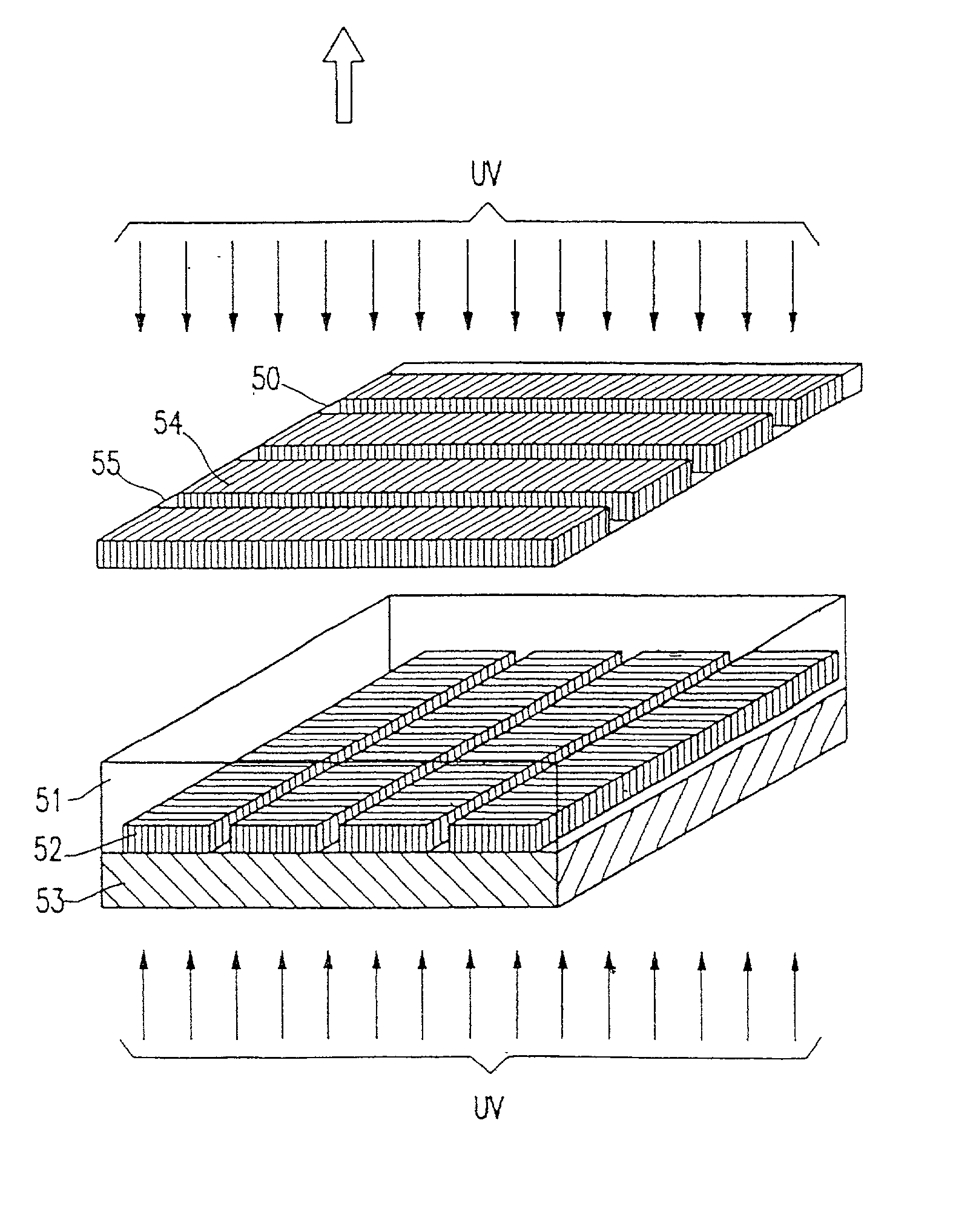
Preparation of Microcups by Microembossing
[0086] The composition shown in Table 1 was Myrad bar #6 coated onto a 2 mil PET film coated with an ITO conductor layer from Sheldahl (Northfield, Minn.). A pre-patterned (4.times.4.times.4 microns) cobalt nickel male mold and a mold release Frekote 700-NC from Henkel were used for microembossing. The coating thickness was controlled to be about 5 microns. The coated film is then embossed by the stencil using a pressure roller at 90.degree. C. The coating is then UV-cured for about 1 minute through the Mylar film using a Cure Zone exposure unit (ADAC Technologies) equipped with a metal fluoride lamp with an intensity of 80 mW / cm.sup.2 at 365 nm. The embossed film is then released from the mold to reveal well-defined (4.times.4.times.4 microns) microcups. The microembossing was carried out using the GBC Laminator at 90.degree. C.
1TABLE 1 UV-curable Acrylate Formulation for Microcups No. Description Ingredient Supplier Parts 1 Epoxy acrylate ...
example 2
Preparation of Microcups by Microembossing
[0087] The same as Example 1 except the formulation shown in Table 2 was coated embossed with a male mold of 4.times.4.times.4 microns.
2TABLE 2 UV-curable Acrylate Formulation for Microcups No. Description Ingredient Supplier Parts 1 Epoxy acrylate Ebecryl 600 UCB Chemicals 50 2 Polyester acrylate Ebecryl 830 UCB Chemicals 15 3 Urethane acrylate Ebecryl 6700 UCB Chemicals 10 4 Silicon acrylate Ebecryl 350 UCB Chemicals 5 5 Monomer Poly(ethylene Aldrich 5 glycol) methacrylate 6 Monomer Sartomer SR238 Sartomer 5 7 Monomer Sartomer SR306 Sartomer 5 8 Monomer Sartomer SR351 Sartomer 5 9 Photoinitiator Irgacure 907 Ciba 0.5 10 Solvent MEK Aldrich 300
[0088] A Myrad bar # 12 was used. The controlled thickness was 5 microns. The microembossing was carried out using a pressure roller (GBC Laminator) heated at 90.degree. C.
example 3
Preparation of Microcups by Microembossing
[0089] The composition shown in Table 3 was laminated using a pressure roller between a 2 ml PET film precoated with an ITO conductor layer, and a pre-patterned (4.times.4.times.4 microns) cobalt nickel mold. The PET / ITO film was treated a corona discharge (Electro-Technic Products, Model BD-10A, Chicago, Ill.) for 5 sec. The cobalt nickel mold was pretreated with a mold release Frekote 750-NC. The coating was then UV cured for 1 min through the PET / ITO film. The embossing film was then released from the mold to reveal well-defined (4.times.4.times.4 microns) microcups with a thickness of 5.5 microns as measured by a Mituyoto thickness gauge.
3TABLE 3 UV-curable Acrylate Formulation for Microcups No. Description Ingredient Supplier Parts 1 Epoxy acrylatel Ebecryl 600 UCB Chemicals 40 2 Polyester acrylate Ebecryl 830 UCB Chemicals 15 3 Urethane acrylate Ebecryl 6700 UCB Chemicals 10 4 Silicon acrylate Ebecryl 350 UCB Chemicals 5 5 Monomer Poly...
PUM
| Property | Measurement | Unit |
|---|---|---|
| area | aaaaa | aaaaa |
| area | aaaaa | aaaaa |
| depth | aaaaa | aaaaa |
Abstract
Description
Claims
Application Information