Process for the conditioning of polluted water

Inactive Publication Date: 2002-10-24
DEGUSSA AG
View PDF6 Cites 30 Cited by
  • Summary
  • Abstract
  • Description
  • Claims
  • Application Information

AI Technical Summary

Problems solved by technology

Using hydrogen peroxide by itself as a treatment can not satisfactorily eliminate pollutants from water.
However, one disadvantage of the radiation-induced activation of hydrogen peroxide is that the radiation does not penetrate far enough into most of the effluents to be treated.
Therefore, this method bears a burden of high technical costs in order to adequately eliminate pollutants from water.
The technology of the process is very costly because the plant has both a reactor cascade, a reactor to neutralize the strongly acid-treated water and a combination of a sedimentation tank and a chamber filter press for separation of the iron hydroxide deposit formed as a byproduct of the reaction.
A disadvantage is that this results in considerable salinization of the treated water and considerable quantities of a sparingly soluble iron hydroxide deposit are also produced, which must be separated off.
A further disadvantage is the use

Method used


Image

  • Process for the conditioning of polluted water
  • Process for the conditioning of polluted water
  • Process for the conditioning of polluted water

Examples


Example

Example 1

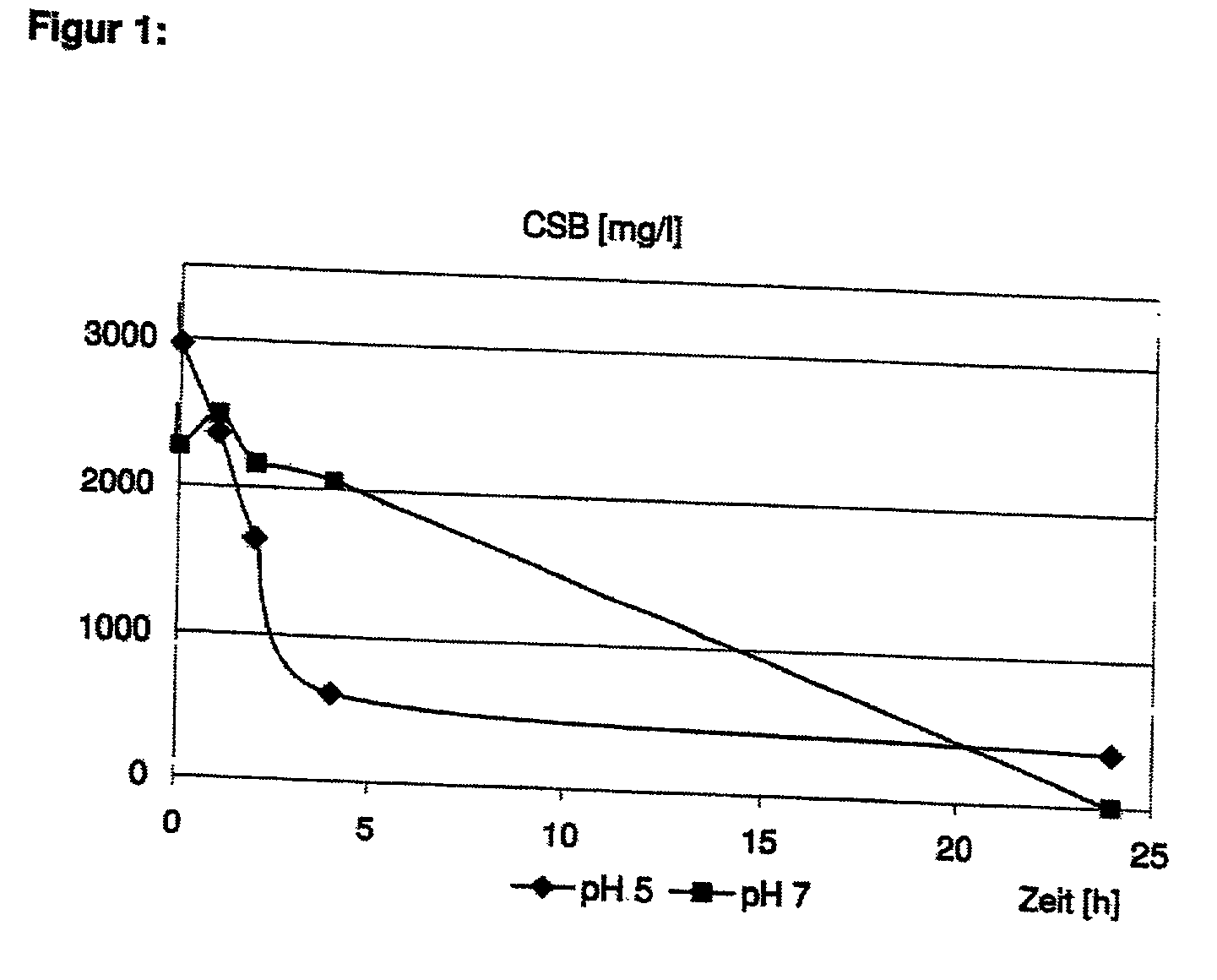
[0055] 2.5 L of a model effluent containing 1050 mg / l 2-chlorophenol (equivalent to a COD of 2500 mg / l) were added to a thermostatic suspension reactor and heated to a starting temperature (see below, 30.degree. C. or 60.degree. C.). 2 g / l of a granulated iron(III)hydroxide containing approximately equal quantities of Fe(OH).sub.3 and Fe(O)OH and 50 wt. % free moisture (GEH, Osnabruick) and hydrogen peroxide at a stoichiometry of 1.6 in relation to the initial COD value, were then added. The pH value of the model effluent was set to pH 5 or pH 7. The model effluent was not buffered. The residual COD was analysed after various reaction times.

[0056] At pH 7, virtually complete oxidation of the COD after 24 hours was observed. At pH 5, 70-80% of the COD had already been oxidized within the first 4 hours. During these 4 hours, approximately 10% iron was released.

[0057] The results of Example 1 are represented in FIG. 1.

Example

Example 2

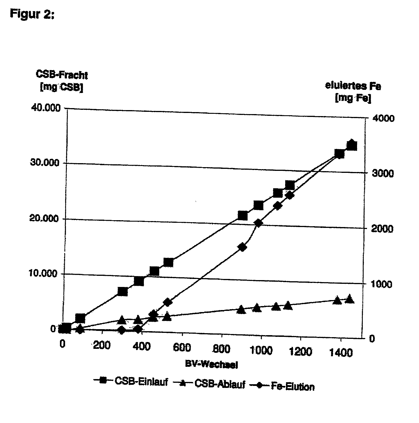
[0058] A glass column was filled with approximately 80 g of granulated iron hydroxide according to example 1 (bed volume approx. 76 cm.sup.3) and continuously trickled from above, at room temperature, with a model effluent containing approximately 100 mg / l 3-chlorobenzoate (equivalent to a COD of 320 mg / l). The pH value was not set, the model effluent had a pH of 6-7. Hydrogen peroxide was added in a concentration of approximately 1.0 g / l to the model effluent. Over a period of approximately 1400 bed volume changes, no break-through of the COD was observed. The degree of oxidation over this period was consistently approximately 80%. During treatment, there was only slight elution of iron, substantially in proportion to the quantity of effluent treated.

[0059] The results of Example 2 are represented in FIG. 2.

Example

Example 3

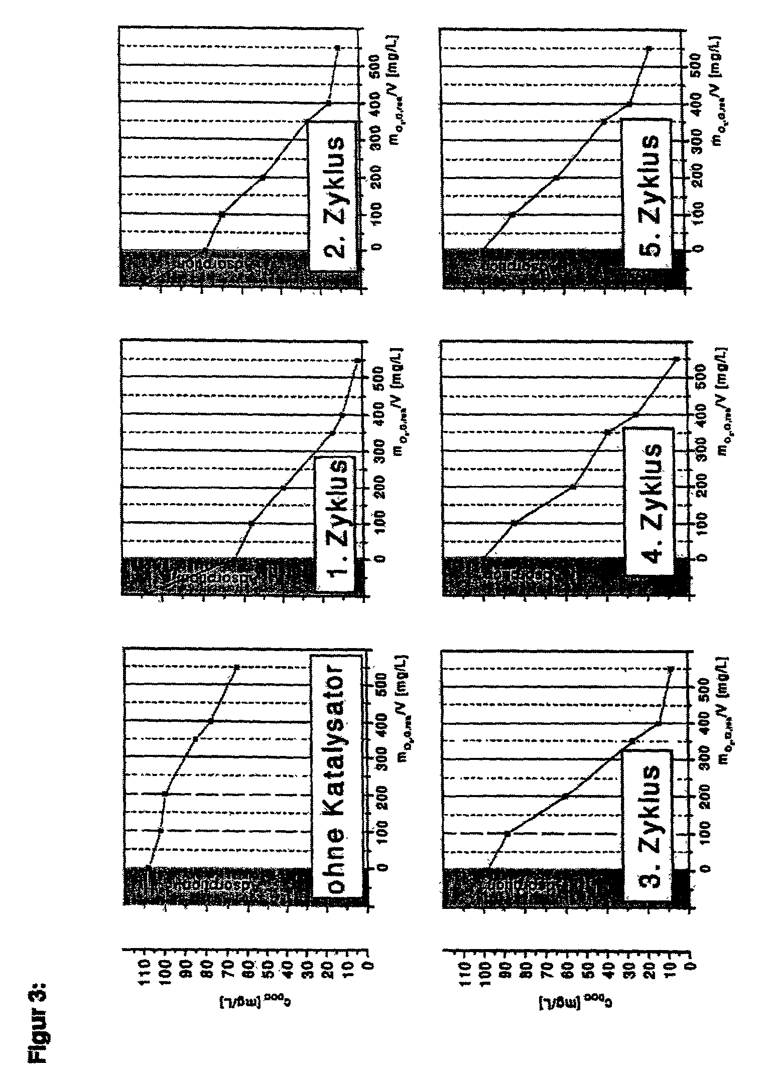
[0060] The combined use of ozone and hydrogen peroxide in the presence of a moulded iron(III)hydroxide-iron(III)oxide hydrate catalyst was investigated. For this purpose, 400 mL model effluent was placed in a bubble column with 3-chlorobenzoic acid in a quantity equivalent to a dissolved organic carbon (DOC) of 108 mg / l. 30 g / l catalyst was added and this was fumigated with air for 15 minutes. Then, the dissolved organic carbon (DOC) was determined. It was then ozonized for 15 minutes with 0.67 g O.sub.3 / minute. A 10% solution of hydrogen peroxide was then added to the reactor through a hose pump, in proportion to the ozone mass flow, at a rate of 0.2 g H.sub.2O.sub.2 / minute. The DOC was determined at various times and plotted as a function of the quantity of ozone consumed up to this time. The solution was then poured off and a fresh 3-chlorobenzoate solution was again added to the catalyst recovered. This cycle was repeated four times.

[0061] The results of the 5 cycles ac...


PUM


Abstract

The invention relates to a process for the treating or conditioning of polluted water using a source of hydrogen peroxide and/or ozone and a heterogeneous catalyst.

Description

BACKGROUND OF INVENTION[0001] 1. Field of the Invention[0002] The invention relates to a process for the treating or conditioning of water and comprises contacting water with a source of hydrogen peroxide, ozone, or mixtures thereof in the presence of a heterogeneous catalyst.[0003] 2. Discussion of the Background[0004] A wide variety of processes and are used to purify water, especially effluent. Examples of such processes include chemical-physical processes and adsorptive processes. Chemical-physical processes include precipitation and flocculation. Adsorptive processes include those using activated carbon. Finally pollutants may be removed by biodegradation or oxidation of the pollutants directly.[0005] Recently, technologies in which pollutants are oxidized have been adopted for the treatment of effluent. Such technologies include oxidation of pollutants using highly reactive hydroxyl radicals which may be produced by various means. These technologies can be photolytic in nature...

Claims


Application Information

Patent Timeline
IPC IPC(8): C01G49/02C02F1/44C02F1/52C02F1/66C02F1/72C02F1/78
CPCC02F1/444C02F1/5236C02F1/66C02F1/722C02F2103/34C02F1/78C02F2101/36C02F2103/14C02F2103/30C02F1/725
Inventor HEMPEL, DIETMARKRULL, RAINERJUNG, THOMASPREUSS, ANDREARASCHKE, HENNINGSEPP, GERHARDWOYCIECHOWSKI, MATTHIAS
Owner DEGUSSA AG
Why Eureka
Try Eureka