Method of butt-welding hot-rolled steel materials by laser beam and apparatus therefor

a hot-rolled steel and laser beam technology, applied in welding/cutting media/materials, manufacturing tools, welding apparatus, etc., can solve the problems of decreasing increasing the depth of penetration d temporarily, and reducing the depth of penetration, so as to achieve sufficient reducing ability, high reducing ability, and reducing ability of metal elements.

Inactive Publication Date: 2003-02-27
NIPPON STEEL CORP
View PDF5 Cites 30 Cited by
  • Summary
  • Abstract
  • Description
  • Claims
  • Application Information

AI Technical Summary

Benefits of technology

0046] In order to achieve the first object by preventing formation of blow holes in the weld bead, in a method of butt-welding hot-rolled bars by a laser beam according to the third invention, the method comprises conducting laser welding while a filler wire of an iron series base material, containing from 0.05 to 3% of one or at least two elements selected from aluminum, silicon, titanium and manganese, is being supplied to the welding portion.
0047] It is essential that the filler wire metal components form oxides which are not evaporated, and it is necessary that the filler wire metal components contain metal which is highly reactive with oxygen (having a high reducing ability). Accordingly, it is necessary that the filler wire contain a simple substance of aluminum, silicon, titanium or manganese, or a combination of at least two of these simple substances at least in a given amount. The lower limit of the content of these components is defined to be 0.05% because the filler wire cannot show a sufficient reducing ability when the content is less than 0.05%. Moreover, the upper limit is defined to be 3% because the weld zone is drastically embrittled when the content exceeds 3%, and because there is the possibility that the weld zone may be fractured during rolling in the latter process.
0048] The filler wire metal supplied to the welding portion is melted in a mixture of a molten portion of the workpiece, which is a component of the bead, and scales. As a result, the reducing ability of a metal element such as aluminum prevents a reaction between carbon and oxygen in the scales which mainly causes formation of blow holes, and no carbon monoxide gas is generated. Moreover, even when there are gaps in the groove portion because of the presence of recesses and protrusions, the filler wire metal is embedded in the recessed and protruded portions by the supply of the filler wire, and no lack of penetration is produced.
0049] In the method of butt-welding hot-rolled steel materials described above, the filler wire can be supplied to a laser-induced plasma in front of the laser beam irradiation portion, in the welding direction. The filler wire i

Problems solved by technology

When the amount of the plasma is increased, the laser beam LB is absorbed by the plasma, and the laser beam LB cannot reach the workpiece S, thereby decreasing the depth of penetration d. On the other hand, when the amount of the plasma is decreased, the laser beam LB easily reaches the workpiece S to cause spiking, thereby increasing the depth of penetration d temporarily.
When the increase and decrease in the depth of penetration are significant, ensuring a bonding area ratio which is aimed at non-fracture of the joint during rolling becomes very difficult in cases where the steel materials are butt welded after shearing in continuous hot rolling.
Although laser welding is suitable as tack welding in a hot rolling line in view of its high speed and its deep penetrating ability, it has the disadvantage of easily forming an offset.
However, even the method mentioned above cannot solve the problems of spiking and generation of meltdown.
However, when the content of a deoxidizing agent is low, blow holes are sometimes included in the weld zone.
However, all these countermeasures are taken at the cost of the ability of deep penetration and the ability of high speed working which are advantages proper to laser welding, and they are unavoidably disadvantageous in view of the bonded area ratio or the productivity.
That is, melting and mixing the filler wire and the base metal uniformly and in suitable amounts over the entire width of the strips have been very difficult for reasons explained below.
(1) Because a gap between groove faces of strips is as very narrow, from 0.05 to 2.00 mm, positional control of the filler wire is difficult.
(2) Because the focus diameter of the laser beam is as very small, from 0.1 to 0.8 mm, positional control of the filler wire is difficult as mentioned above.
As a result, complete straightening of the coiling set of the filler wire cannot be achieved by a filler supply nozzle having a linear shape.
Positional control of the filler wire is therefore difficult, and moreover the coiling set changes as the filler wire is coiled.
For reasons explained abo

Method used


Image

  • Method of butt-welding hot-rolled steel materials by laser beam and apparatus therefor
  • Method of butt-welding hot-rolled steel materials by laser beam and apparatus therefor
  • Method of butt-welding hot-rolled steel materials by laser beam and apparatus therefor

Examples


example 2

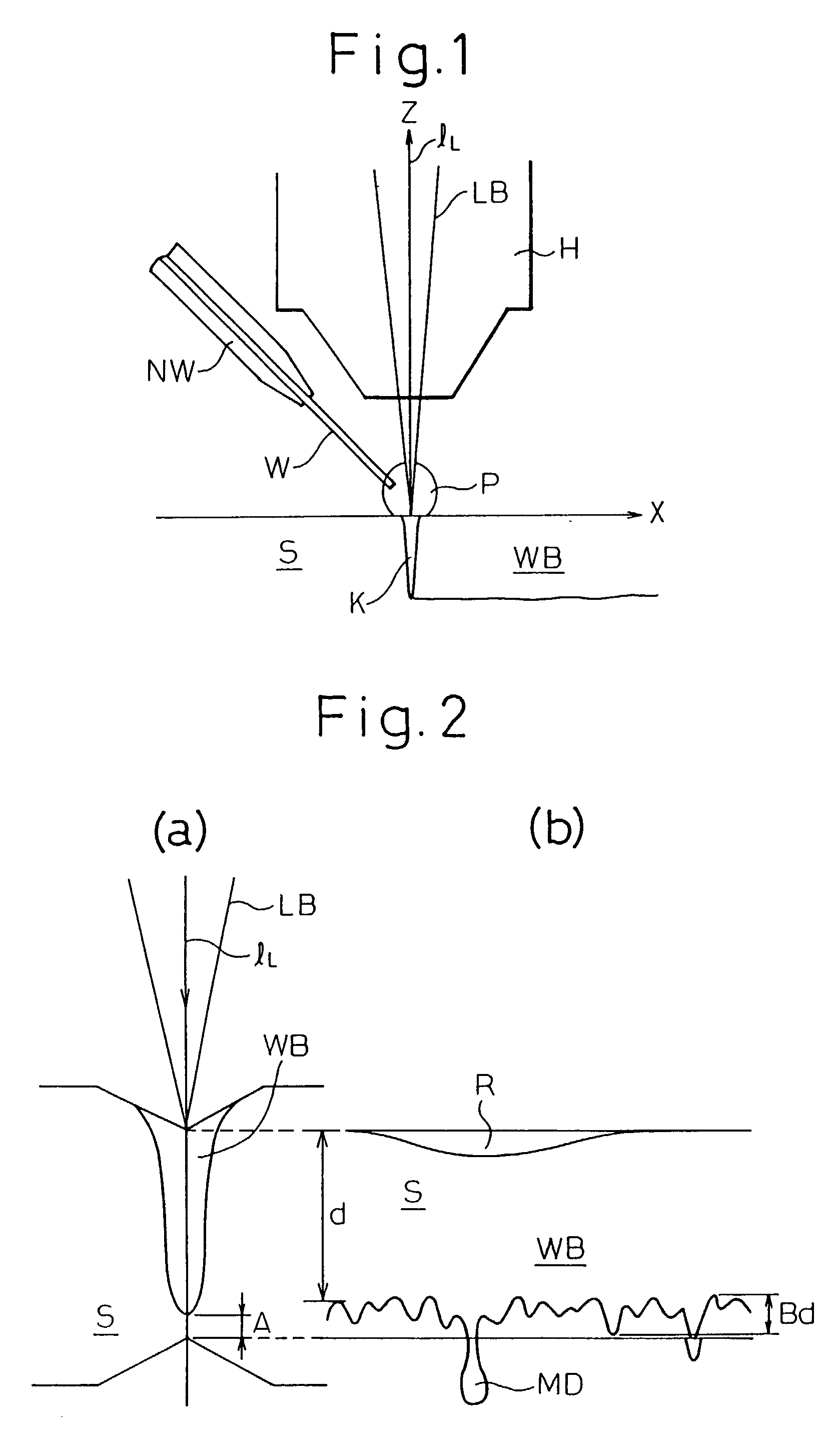
[0101] SS 41 steel materials at about 1,000.degree. C. were tack-welded, using a 45 kW CO.sub.2 gas laser, according to the second invention. In order to shield the welding atmosphere from the air, welding was conducted while helium was being blown as a shield gas. Moreover, welding was conducted at a welding speed of 3 m / min while the laser beam was oscillated at a frequency of 50 Hz at an amplitude of 0.4 mm. As a result of conducting tack welding with laser as explained above, the variation ratio (Bd / d) thus obtained was about 7%. On the other hand, when the same SS 41 materials were tack-welded by laser by a conventional method wherein the laser beam was not oscillated, and the other conditions were the same as those mentioned above, the variation ratio (Bd / d) thus obtained was 15%.

[0102] Furthermore, when hot-rolled steel materials were butt-welded, neither the meltdown of molten metal nor lowering of the bonded area ratio was observed.

[0103] FIG. 17 shows one embodiment of a l...

example 3

[0111] According to the third invention, steel materials at about 1,000.degree. C. were butt-welded by a 45 kW CO.sub.2 gas laser while center gas (helium) was being blown. The welding speed V was 3 m / min. A filler wire containing 3% of Ti was employed, and the filler wire supply speed was determined to be 4 m / min. The variation ratio Bd / d was lowered to about 10% from about 20% which was obtained when the welding was conducted without supplying the filler wire. Moreover, neither meltdown of molten metal in the butt welding portion nor lowering of the bonded area ratio was observed.

[0112] As explained above, according to the third invention, formation of blow holes in the weld bead is prevented; the depth of penetration in the weld bead portion is made uniform; a bead shape with a flat bottom can be obtained without spiking and excessive penetration. Consequently, a defectless butt weld zone is obtained, and the bonding strength is improved.

[0113] The fundamental construction of the...

example 4

[0118] An embodiment of the present invention will be explained by taking bonding of hot-rolled sheet bars as an example. FIG. 24 is a schematic side view of an apparatus for bonding sheet bars provided to a hot rolling facility. FIG. 25 is a plan view of FIG. 24. The front end and the tail end of each of the sheet bars S1, S2 were cut off along the width direction by a flying shear 305 to form groove faces. The sheet bars S1, S2 each had a length of 30 m, a width of 1,100 mm and a thickness of 35 mm. Moreover, the sheet bars S1, S2 had a temperature of 1,000.degree. C., and their transfer speed was 90 m / min. The time from shearing to the start of welding was about 20 sec, and the thickness of the scales thus formed on the welding surface was about 50 .mu.m. The tail end face of the preceding sheet bar S1 and the front end face of the following sheet bar S2 were then butted with each other, and the butt portion 305 was welded by moving a welding head 339 along the butt portion 305, ...


PUM

PropertyMeasurementUnit
Lengthaaaaaaaaaa
Fractionaaaaaaaaaa
Angleaaaaaaaaaa

Abstract

In order to make the depth of penetration in the weld bead portion uniform and obtain a bead shape having a flat bottom without spiking and meltdown during continuous hot rolling by bonding a plurality of hot-rolled steel materials using a laser beam, the following methods are employed: (A) a method of butt welding wherein center gas is blown against the welding portion symmetrically to the optical axis of the laser beam while side gas is being blown thereagainst from the side, the method comprising conducting welding while the center of laser-induced plasma is shifted in the welding direction from the center of the laser beam by a distance 0.2 to 0.5 times as much as a reference plasma diameter determined from the laser output and the beam diameter, and the type and flow rate of the center gas; or (B) a method comprising scanning the butt line with the laser beam during the laser welding at a speed of 2 to 10 m/min, and simultaneously oscillating the laser beam in the direction vertical to the butt line at a frequency of 40 to 80 Hz at an amplitude of 0.4 to 1.0 mm. Alternatively, (C) in order to prevent formation of blow holes in the weld bead, to make the depth of penetration in the weld bead portion uniform, and to obtain a bead shape having a flat bottom without spiking and excessive penetration, laser welding is conducted while a filler wire of an iron series base material, containing from 0.05 to 3% of one or at least two elements selected from aluminum, silicon, titanium and manganese, is being supplied to the welding portion. Moreover, (D) in order to stably supply a filler wire to the butt portion with high supply accuracy, the filler wire W is passed through a wire supply nozzle having a curved portion, and the filler wire is supplied toward the welding point along the welding line.

Description

[0001] The present invention relates to a method of butt-welding hot-rolled steel materials by a laser beam, during the production of a hot-rolled steel plate or a hot-rolled steel strip by continuously hot-rolling a steel material such as a slab or a sheet bar, and a welding nozzle, a filler wire supply nozzle and a welding apparatus.[0002] In order to continuously hot-roll a steel material such as a slab or a sheet bar in a hot rolling line, the tail end of the preceding steel material has been butt-welded (tack welding) to the front end of the following steel material by a laser beam.[0003] As shown in FIG. 1, the principle of a method of welding by a laser beam LB, which is a high energy beam, is to irradiate a workpiece S with a focused laser beam LB while a filler wire W is being supplied from a wire supply nozzle NW, thereby forming a keyhole K as a heat source which is a region having the highest energy density, and to scan the keyhole.[0004] When the keyhole K which is a re...

Claims


Application Information

Patent Timeline
IPC IPC(8): B23K26/14B23K26/26B23K35/30
CPCB23K26/1435B23K26/1441B23K26/1447B23K26/1452B23K26/147B23K26/26B23K35/3053B23K2203/04B23K26/1437B23K26/1436B23K26/1438B23K2103/04
Inventor MINAMIDA, KATSUHIROYAMAMOTO, HIROYUKIKIDO, MOTOI
Owner NIPPON STEEL CORP
Why Eureka
Try Eureka