Electrolytic copper-plated r-t-b magnet and plating method thereof

Inactive Publication Date: 2003-03-20
HITACHI METALS LTD
View PDF2 Cites 14 Cited by
  • Summary
  • Abstract
  • Description
  • Claims
  • Application Information

AI Technical Summary

Benefits of technology

0009] Accordingly, an object of the present invention is to provide a method for forming an electrolytic copper plating layer having a substantially uniform thickness and excellent scratch resistanc

Problems solved by technology

However, because copper cyanide is extremely toxic, the highest attention should be paid to the safety of production, the control of plating solutions, and the treatment of waste water.
It has been found, however, that when these electrolytic copper plating solutions are used for R--Fe--B magnets, metal elements in the R--Fe--B magnets are dissolved or subjected to a substitution reaction, resulting in electrolytic copper plating layers have poor adhesion to the R--Fe--B magnet and magnets without high thermal demagnetization resistance.
However, because the first layer is an electroless copper plating layer in this method, it is not only poor in adhesion to the R--Fe--B magnet, but also it is easily self-decomposed because it is more unstable than the electrolytic plating solution.
However, in

Method used


Image

  • Electrolytic copper-plated r-t-b magnet and plating method thereof
  • Electrolytic copper-plated r-t-b magnet and plating method thereof
  • Electrolytic copper-plated r-t-b magnet and plating method thereof

Examples


example 1

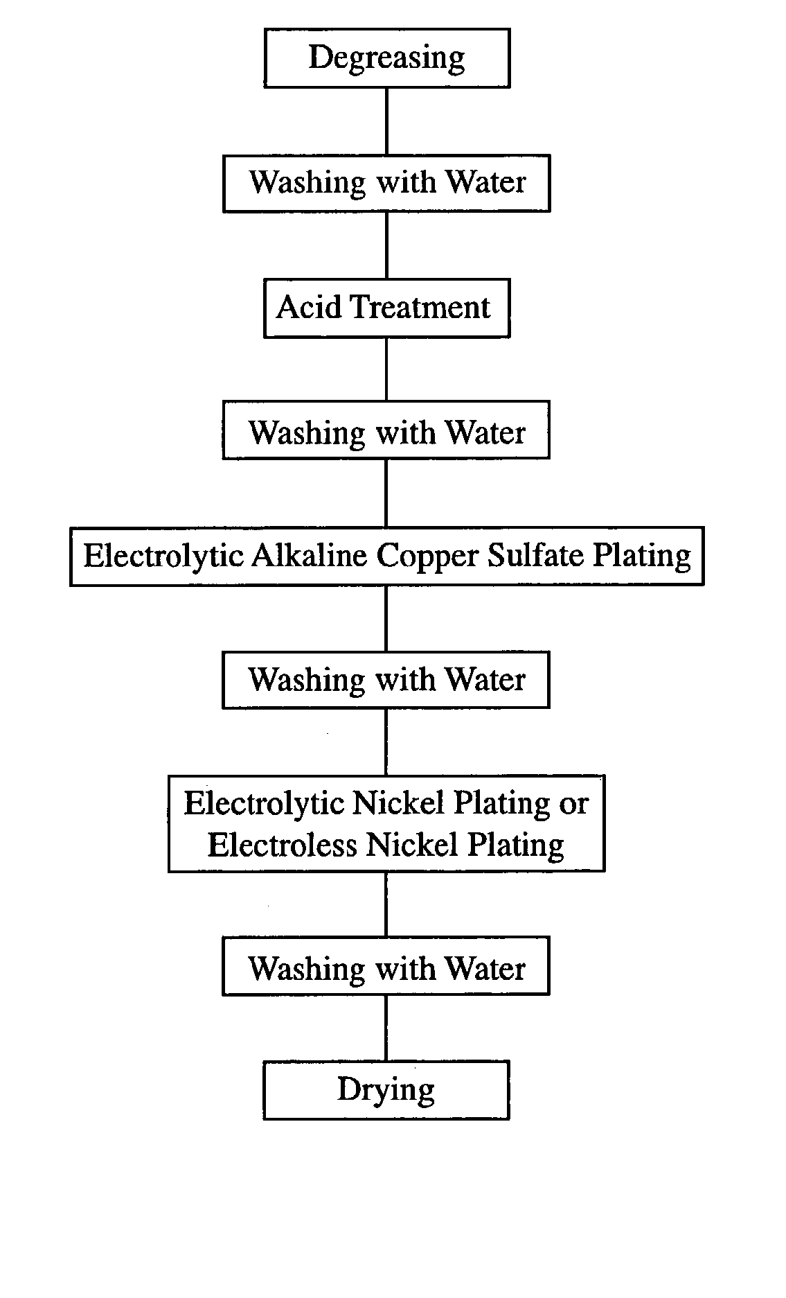
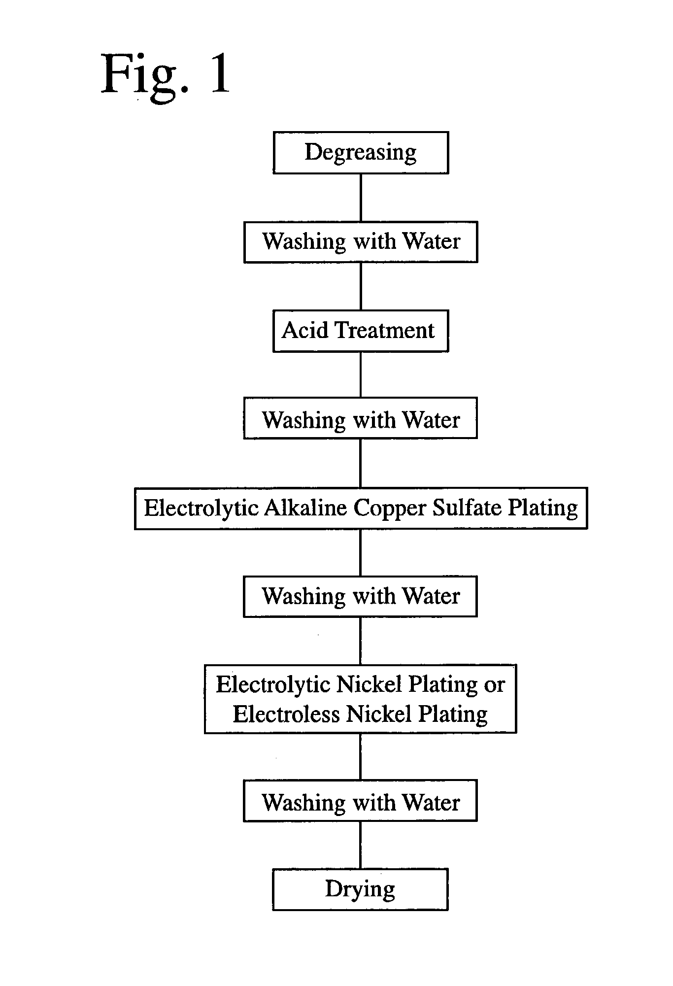
[0068] Each of rectangular plate-shaped R--T--B sintered magnets of 10 mm in length, 70 mm in width and 6 mm in thickness with anisotropy in the thickness direction, which had a main component composition (weight %) comprising 25.0% of Nd, 5.0% of Pr, 1.5% of Dy, 1.0% of B, 0.5% of Co, 0.1% of Ga, 0.1% of Cu and 66.8% of Fe, was provided with an electrolytic copper plating layer and an electrolytic nickel layer by the plating method shown in FIG. 1. The plating processes were as follows.

[0069] First, each R--T--B magnet was degreased by a degreasing agent (trade name: Z-200, available from World Metal Co. Ltd.) at 30.degree. C. for 1 minute, and then washed with water. Next, each R--T--B magnet was immersed in a diluted nitric acid bath at room temperature for 2 minutes to carry out an acid treatment, and then washed with water to clean the surface of each R--T--B magnet.

[0070] A barrel tank containing the cleaned R--T--B magnets was immersed in an alkaline copper sulfate plating ba...

example 2

[0080] An R--T--B magnet was provided with an electrolytic copper plating layer and then washed with water in the same manner as in EXAMPLE 1. The copper-plated R--T--B magnet was immersed in an electroless nickel plating solution (trade name: NIBODULE, available from Okuno Chemical Industries Co. Ltd.) at 80.degree. C. for 60 minutes, and then washed with water and dried to form an electroless nickel plating layer having an average thickness of 8 .mu.m. The resultant Cu / Ni-plated R--T--B magnet was evaluated in the same manner as in EXAMPLE 1. The results are shown in Table 1. The results of the peel test revealed that peeling took place in an interface between the magnet substrate and the electrolytic copper plating layer in any samples. Also, the samples cooled to room temperature for the measurement of a thermal demagnetization ratio had good appearance.

[0081] A sample with an exposed electrolytic copper plating layer was formed from the Cu / Ni-plated R--T--B magnet in the same m...

example 3

[0082] An R--T--B magnet was provided with an electrolytic copper plating layer and then washed with water in the same manner as in EXAMPLE 1. The copper-plated R--T--B magnet was immersed in an electroless nickel plating solution (trade name: Top Nicoron F153, available from Okuno Chemical Industries Co. Ltd.) at 90.degree. C. for 60 minutes, and then washed with water and dried, to form an electroless nickel plating layer having an average thickness of 8 .mu.m. The resultant Cu / Ni-plated R--T--B magnet was evaluated in the same manner as in EXAMPLE 1. The results are shown in Table 1. The results of the peel test revealed that peeling took place in an interface between the magnet substrate and the electrolytic copper plating layer in any samples. Also, the samples cooled to room temperature for the measurement of a thermal demagnetization ratio had good appearance.

[0083] A sample with an exposed electrolytic copper plating layer was formed from the Cu / Ni-plated R--T--B magnet in t...


PUM

PropertyMeasurementUnit
Densityaaaaaaaaaa
Densityaaaaaaaaaa
Fractionaaaaaaaaaa

Abstract

An R-T-B magnet (R is at least one kind of rare-earth elements including Y, and T is Fe or Fe and Co.) has an electrolytic copper-plating film where the ratio [I(200)/I(111)] of the X-ray diffraction peak intensity I(200) from the (200) plane to the X-ray diffraction peak intensity I(111) from the (111) plane is 0.1-0.45 in the X-ray diffraction by CuKal rays. This electrolytic copper-plating film is formed by an electrolytic copper-plating method using an electrolytic copper-plating solution which contains 20-150 g/L of copper sulphate and 30-250 g/L of chelating agent and contains no agent for reducing copper ions and has a pH adjusted to 10.5-13.5.

Description

[0001] The present invention relates to an R--T--B magnet provided with a electrolytic copper plating layer having a substantially uniform thickness and excellent scratch resistance free from pinholes, and a method for forming such an electrolytic copper plating layer on the R--T--B magnet using an electrolytic copper plating solution containing no cyanides.[0002] An R--Fe--B magnet containing an R.sub.2Fe.sub.14B intermetallic compound as a main phase, wherein R is at least one of rare earth elements including Y, is usually plated because of poor oxidation resistance. Though plating metals are generally nickel, copper, etc., the R--Fe--B magnet is eroded by a nickel plating solution in direct contact, because the nickel plating solution is acidic. Accordingly, it is general to form a nickel plating layer on the surface of the R--Fe--B magnet after forming a copper plating layer thereon as a primer layer.[0003] From the aspect of improving adhesion to a magnet substrate and preventi...

Claims


Application Information

Patent Timeline
IPC IPC(8): C25D3/38C25D7/00H01F41/02
CPCC25D3/38Y10T428/12944Y10S428/935C25D7/001Y10T428/12708Y10T428/12792Y10T428/12715Y10T428/12701Y10T428/12785Y10T428/12903Y10T428/12889Y10T428/12875Y10T428/1291Y10T428/12896H01F41/026
Inventor ANDO, SETSUOENDOH, MINORUNAKAMURA, TSUTOMUFUKUSHI, TORU
Owner HITACHI METALS LTD
Why Eureka
Try Eureka