Method for manufacturing ferroelectric thin film device, ink jet recording head, and ink jet printer

a technology of ferroelectric thin film and recording head, which is applied in the direction of printing, nanotechnology, transistors, etc., can solve the problems of difficult to control the orientation of a ferroelectric thin film according to the intended application of the ferroelectric thin film, the bottom electrode took in oxygen and swelled in the course of the baking of the pzt film, and the bottom electrode became hard and brittl

Inactive Publication Date: 2003-04-17
SEIKO EPSON CORP
View PDF1 Cites 8 Cited by
  • Summary
  • Abstract
  • Description
  • Claims
  • Application Information

AI Technical Summary

Benefits of technology

[0020] Yet another object of the present invention is to provide a method for manufacturing an electromechanical transducer having very reliable drive characteristics when iridium alone is used as the material for the bottom electrode.
[0021] Yet another object of the present invention is to provide an electromechanical transducer with which adhesion with the installation surface can be enhanced without diminishing the piezoelectric characteristics, and an ink jet recording head and an ink jet printer that make use of this transducer. Another object of the present invention is to provide a method for manufacturing an electromechanical transducer having a layer structure with which adhesion with the installation surface can be maintained without diminishing the piezoelectric characteristics.
[0022] Still another object of the present invention is to provide an electromechanical transducer having good piezoelectric characteristics as a result of reduced residual stress during baking, an ink jet recording head and printer that make use of this electromechanical transducer, and a method for manufacturing an electromechanical transducer.
[0031] The oxygen content of the bottom electrode in the course of baking the ferroelectric thin film can be kept to a minimum and an electromechanical transducer with excellent toughness can be provided by adjusting the thickness of the titanium layer laminated over the bottom electrode to within a range of at least 15 nm and no more than 30 nm.

Problems solved by technology

However, even though it was possible to form a ferroelectric thin film with excellent orientability by optimizing the conditions that affect the orientation of a ferroelectric thin film by means of the bottom electrode (or substrate), such as matching the lattice constants of the bottom electrode (or substrate) and the ferroelectric thin film, as with the above-mentioned prior art, it was difficult to control the orientation of a ferroelectric thin film as desired according to the intended application of the ferroelectric thin film.
Also, the technology disclosed in Japanese Patent Laid-Open No.08-335676 allows crystals to be grown around nuclei and good contact with a PTZ film ensured by forming nuclei of a component element of PZT (titanium) on the bottom electrode, but if iridium alone was used as the bottom electrode and the PZT film was formed by sol-gel method, then there was a problem in that the bottom electrode took in oxygen and swelled in the course of the baking of the PZT film.
Because the bottom electrode became hard and brittle if it took in oxygen, the bottom electrode would break if used as an actuator.
The reason for this seems to be that the titanium becomes admixed with the ferroelectric thin film and disrupts the stoichiometric ratio in this film, or produces a layer with a low dielectric constant at the interface between the bottom electrode and the ferroelectric thin film.
However, the bottom electrodes composed of an alloy of platinum and iridium, iridium alone, or iridium oxide that were used for memory devices posed problems when used as electromechanical transducers, such as in an ink jet recording head.
Specifically, the electromechanical transducer must itself be deformed with an ink jet recording head, but with a bottom electrode containing iridium, there were problems in that the bottom electrode was too hard and the film stress generated in the bottom electrode was too high.
Another problem was poor adhesion between the bottom electrode and the installation surface and between the bottom electrode and the ferroelectric thin film.
Furthermore, the problem of markedly increased leakage current was encountered when iridium was used as the bottom electrode, as discussed in the article "Explanation of the Leakage Mechanism of a PZT Capacitor Deposited on an Ir Electrode (Lecture Summaries from the 59.sup.th Convention of the Applied Physics Society, issued Sep. 15, 1998, p.
When an alloy of platinum and iridium was used for the bottom electrode of an electromechanical transducer as disclosed in Japanese Patent Laid-Open No.07-245236, or when iridium oxide was used as disclosed in Japanese Patent Laid-Open No.07-245237, a problem was encountered in that residual stress was generated in the bottom electrode containing iridium in the course of baking and crystallizing the ferroelectric thin film, and this residual stress diminished the characteristics of the electromechanical transducer.
For example, the residual stress generated in a bottom electrode could impart strain to the ferroelectric thin film and undesirably lower the percentage of volumetric change.

Method used


Image

  • Method for manufacturing ferroelectric thin film device, ink jet recording head, and ink jet printer
  • Method for manufacturing ferroelectric thin film device, ink jet recording head, and ink jet printer
  • Method for manufacturing ferroelectric thin film device, ink jet recording head, and ink jet printer

Examples


embodiment 2

[0101] Embodiment 2 of the Invention

[0102] A ferroelectric thin film has an extremely large dielectric constant, ranging from a few hundred to a few thousand, and when used for the insulating film of a capacitor, the resulting capacitor has a small surface area and large capacity that are favorable for circuits of large-scale integration. A ferroelectric thin film has spontaneous polarization, and because the polarization direction can be inverted by the action of an external electrical field, this characteristic can be utilized to manufacture a nonvolatile memory. An FRAM in which a ferroelectric thin film such as this is used as the capacitor insulating film has numerous advantages over a conventional nonvolatile memory, such as better nonvolatility, higher operating speed, lower energy consumption, and more rewrites.

[0103] This embodiment pertains to a technique in which a ferroelectric thin film device is utilized as a capacitor for an FRAM memory cell. In specific terms, a film...

embodiment 3

[0108] Embodiment 3 of the Invention

[0109] This embodiment pertains to a technique for manufacturing a ferroelectric thin film device in which iridium alone is used for the bottom electrode. With this embodiment, a bottom electrode composed of iridium alone is formed over a surface preparation layer composed of zirconium oxide. A titanium layer (titanium nucleus), which is the element that constitutes the ferroelectric thin film (piezoelectric film), is then laminated over the bottom electrode, and the thickness of the titanium layer is adjusted to about 15 to 30 nm, which prevents the admixture of oxygen into the bottom electrode during the baking of the ferroelectric thin film in a sol-gel method.

WORKING EXAMPLE

[0110] The steps for manufacturing the electromechanical transducer are more or less the same as the electromechanical transducer manufacturing steps described in Embodiment 1, and the following description will focus on the differences.

[0111] First, as shown in FIG. 3A, a ...

embodiment 4

[0118] Embodiment 4 of the Invention

[0119] This embodiment relates to the bottom electrode of an electromechanical transducer with which adhesion to the installation surface can be enhanced without compromising the piezoelectric characteristics.

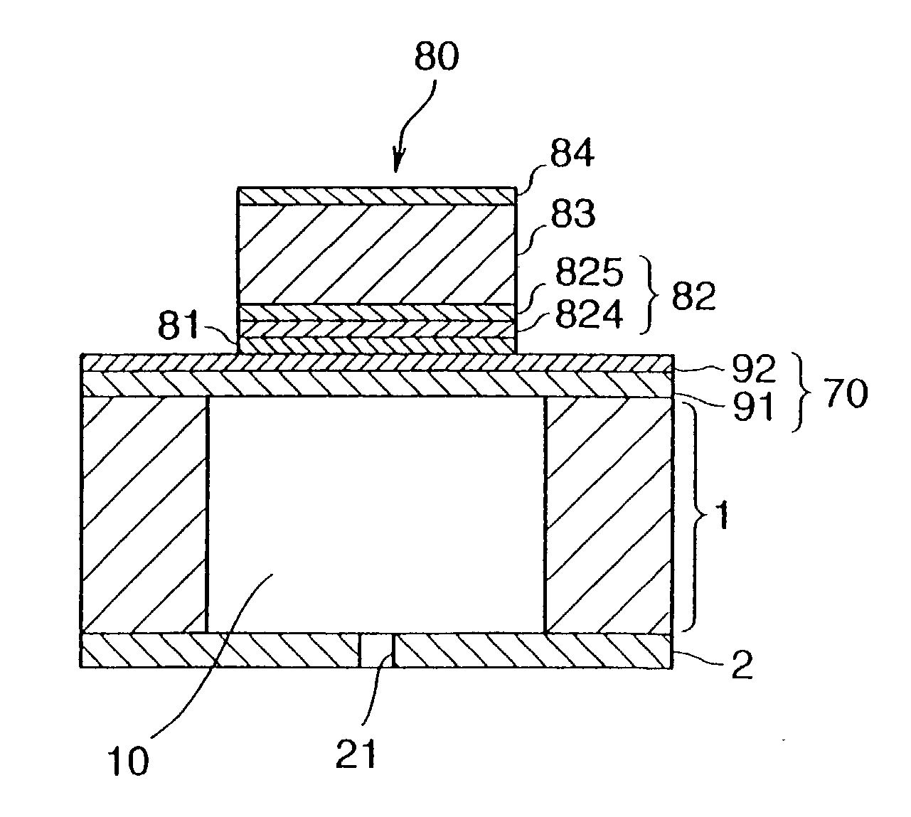
[0120] FIG. 9 is a cross sectional diagram illustrating the layer structure when the electromechanical transducer pertaining to this embodiment is formed over an installation surface. As shown in the figure, an electromechanical transducer 40 is produced by the successive lamination of an adhesive layer 41, a bottom electrode 42, an anti-diffusion layer 43, a ferroelectric thin film (piezoelectric film) 44, and a top electrode 45 over the installation surface. There are no particular restrictions on the installation surface, but in this embodiment it corresponds to the diaphragm of an ink jet recording head (for instance, a silicon oxide film or a laminate structure of a silicon oxide film layer and a zirconium oxide film).

[0121] The adhesive...


PUM

PropertyMeasurementUnit
thicknessaaaaaaaaaa
thicknessaaaaaaaaaa
thicknessaaaaaaaaaa

Abstract

It is an object of the present invention to control the crystal orientation of a ferroelectric thin film as dictated by the application of a ferroelectric thin film device. To accomplished the stated object, a bottom electrode containing at least iridium is formed over a surface preparation layer whose main component is zirconium oxide, and an ultra-thin titanium layer is laminated over the bottom electrode. An amorphous layer containing the elemental metal and elemental oxygen that constitute the ferroelectric is formed over the titanium layer, and a crystallized ferroelectric thin film is formed by heat treating this amorphous layer. If the thickness of the titanium layer is kept between 2 nm and 10 nm in the lamination thereof, the ferroelectric thin film will have a priority orientation of (100), and if it is kept between 10 nm and 20 nm, the ferroelectric thin film will have a priority orientation of (111).

Description

[0001] 1. Field of the Invention[0002] The present invention relates to ferroelectric thin film device that functions as a piezoelectric device, a nonvolatile ferroelectric memory device, a pyroelectric device, or the like, and more particularly to a technique for controlling the orientation of a ferroelectric thin film, and to a technique for improving the bottom electrode of this ferroelectric thin film device.[0003] 2. Description of the Related Art[0004] Crystalline materials consisting of compound oxides that exhibit ferroelectricity, such as lead titanate zirconate, barium titanate, and lithium niobate, have numerous functions, including spontaneous polarization, a high dielectric constant, an electro-optical effect, a piezoelectric effect, and a pyroelectric effect, and as such are used in the development of a wide range of devices. For instance, the piezoelectric properties of these materials are utilized in capacitors in FRAM (Ferroelectric Random Access Memory), DRAM (Dyna...

Claims


Application Information

Patent Timeline
Patent Type & Authority Applications(United States)
IPC IPC(8): B41J2/055B41J2/045B41J2/135B41J2/14B41J2/145B41J2/16B82Y10/00H01L21/822H01L21/8242H01L21/8246H01L27/04H01L27/105H01L27/108H01L37/02H01L41/09
CPCB41J2/14233B41J2/161B41J2/1623B41J2/1628B41J2/1629H01L41/0973B41J2/1645B41J2/1646H01L41/1876H01L41/318B41J2/1642H10N30/2047H10N30/8554H10N30/078
Inventor MURAI, MASAMI
Owner SEIKO EPSON CORP
Why Eureka
Try Eureka