Method for manufacturing ferroelectric thin film device, ink jet recording head, and ink jet printer

a technology of ferroelectric thin film and recording head, which is applied in the direction of printing, nanotechnology, transistors, etc., can solve the problems of difficult to control the orientation of a ferroelectric thin film according to the intended application of the ferroelectric thin film, the bottom electrode took in oxygen and swelled in the course of the baking of the pzt film, and the bottom electrode became hard and brittl

Inactive Publication Date: 2003-05-15
SEIKO EPSON CORP
View PDF4 Cites 22 Cited by
  • Summary
  • Abstract
  • Description
  • Claims
  • Application Information

AI Technical Summary

Benefits of technology

[0020] Yet another object of the present invention is to provide a method for manufacturing an electromechanical transducer having very reliable drive characteristics when iridium alone is used as the material for the bottom electrode.
[0021] Yet another object of the present invention is to provide an electromechanical transducer with which adhesion with the installation surface can be enhanced without diminishing the piezoelectric characteristics, and an ink jet recording head and an ink jet printer that make use of this transducer. Another object of the present invention is to provide a method for manufacturing an electromechanical transducer having a layer structure with which adhesion with the installation surface can be maintained without diminishing the piezoelectric characteristics.
[0022] Still another object of the present invention is to provide an electromechanical transducer having good piezoelectric characteristics as a result of reduced residual stress during baking, an ink jet recording head and printer that make use of this electromechanical transducer, and a method for manufacturing an electromechanical transducer.
[0031] The oxygen content of the bottom electrode in the course of baking the ferroelectric thin film can be kept to a minimum and an electromechanical transducer with excellent toughness can be provided by adjusting the thickness of the titanium layer laminated over the bottom electrode to within a range of at least 15 nm and no more than 30 nm.

Problems solved by technology

However, even though it was possible to form a ferroelectric thin film with excellent orientability by optimizing the conditions that affect the orientation of a ferroelectric thin film by means of the bottom electrode (or substrate), such as matching the lattice constants of the bottom electrode (or substrate) and the ferroelectric thin film, as with the above-mentioned prior art, it was difficult to control the orientation of a ferroelectric thin film as desired according to the intended application of the ferroelectric thin film.
Also, the technology disclosed in Japanese Patent Laid-Open No. 08-335676 allows crystals to be grown around nuclei and good contact with a PTZ film ensured by forming nuclei of a component element of PZT (titanium) on the bottom electrode, but if iridium alone was used as the bottom electrode and the PZT film was formed by sol-gel method, then there was a problem in that the bottom electrode took in oxygen and swelled in the course of the baking of the PZT film.
Because the bottom electrode became hard and brittle if it took in oxygen, the bottom electrode would break if used as an actuator.
The reason for this seems to be that the titanium becomes admixed with the ferroelectric thin film and disrupts the stoichiometric ratio in this film, or produces a layer with a low dielectric constant at the interface between the bottom electrode and the ferroelectric thin film.
However, the bottom electrodes composed of an alloy of platinum and iridium, iridium alone, or iridium oxide that were used for memory devices posed problems when used as electromechanical transducers, such as in an ink jet recording head.
Specifically, the electromechanical transducer must itself be deformed with an ink jet recording head, but with a bottom electrode containing iridium, there were problems in that the bottom electrode was too hard and the film stress generated in the bottom electrode was too high.
Another problem was poor adhesion between the bottom electrode and the installation surface and between the bottom electrode and the ferroelectric thin film.
Furthermore, the problem of markedly increased leakage current was encountered when iridium was used as the bottom electrode, as discussed in the article "Explanation of the Leakage Mechanism of a PZT Capacitor Deposited on an Ir Electrode (Lecture Summaries from the 59.sup.th Convention of the Applied Physics Society, issued Sep. 15, 1998, p.
When an alloy of platinum and iridium was used for the bottom electrode of an electromechanical transducer as disclosed in Japanese Patent Laid-Open No. 07-245236, or when iridium oxide was used as disclosed in Japanese Patent Laid-Open No. 07-245237, a problem was encountered in that residual stress was generated in the bottom electrode containing iridium in the course of baking and crystallizing the ferroelectric thin film, and this residual stress diminished the characteristics of the electromechanical transducer.
For example, the residual stress generated in a bottom electrode could impart strain to the ferroelectric thin film and undesirably lower the percentage of volumetric change.
The amount added will vary with the system, but if too large, the reaction will proceed too quickly and the resulting film will tend to be uneven, and it will also be difficult to control the reaction velocity.
The reaction will also be difficult to control if the amount of added water is too small, so the proper amount should be used.
The inventors conducted experiments into this, but they have yet to discover a film with which the above-mentioned effect can be obtained on any surface preparation layer other than a zirconium oxide film.
Nor could they obtain the above-mentioned effect with elements other than titanium, such as the other elements that constitute a ferroelectric, including lead and zirconium.
They were unable, however, to obtain this effect with other film formation methods besides a sol-gel method, although they attempted to control the orientation of a PZT film by sputtering, laser ablation, and CVD.
Whereas the crystallization of a PZT film gradually proceeds from the bottom electrode side toward the top electrode side with a sol-gel or MOD process, the crystallization of the PZT film proceeds at random with CVE, sputtering, and so on, and the resulting lack of regularity in crystallization seems to be one likely cause of the difficulty in controlling orientation.
The bottom electrode 71 becomes hard and brittle if it contains oxygen, so the electromechanical transducer may break when used as an actuator.

Method used


Image

  • Method for manufacturing ferroelectric thin film device, ink jet recording head, and ink jet printer
  • Method for manufacturing ferroelectric thin film device, ink jet recording head, and ink jet printer
  • Method for manufacturing ferroelectric thin film device, ink jet recording head, and ink jet printer

Examples


embodiment 5

[0152] Embodiment 5 of the Invention

[0153] This embodiment relates to an electromechanical transducer formed at a relatively low temperature, to a method for manufacturing this electromechanical transducer, and to an ink jet recording head and ink jet printer that make use of the same.

[0154] FIG. 16 is a cross sectional diagram of a layer structure, in which the electromechanical transducer portion of an ink jet recording head in this embodiment has been enlarged.

[0155] As shown in this figure, an electromechanical transducer 80 comprises an interlayer 92, an adhesive layer 81, a bottom electrode 82, a ferroelectric thin film (piezoelectric film) 83, and a top electrode 84, all laminated over an oxide film 91 that forms the installation surface.

[0156] The interlayer 92 is an elastic layer, and together with the oxide film 91, constitutes a diaphragm film 70. The interlayer 92 is formed from a compound selected from the group consisting of zirconium oxide, tantalum oxide, silicon nit...

embodiment 6

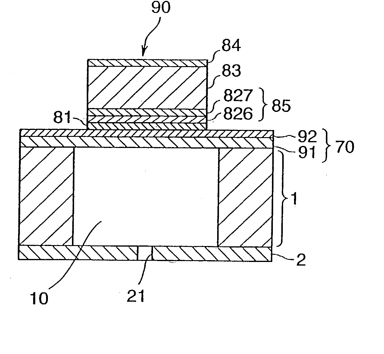
[0182] Embodiment 6 of the Invention

[0183] This embodiment relates to the structure of an electromechanical transducer manufactured when baking is performed at a temperature over 750.degree. C. in the manufacturing process of Embodiment 5.

[0184] FIG. 18 is a cross sectional diagram of the structure of a layer structure, in which the electromechanical transducer portion of an ink jet recording head in this embodiment has been enlarged.

[0185] As shown in this figure, an electromechanical transducer 90 comprises an interlayer 92, an adhesive layer 81, a bottom electrode 85, a ferroelectric thin film (piezoelectric film) 83, and a top electrode 84, all laminated over an oxide film 91 that forms the installation surface.

[0186] The interlayer 92, adhesive layer 81, ferroelectric thin film 83, and top electrode 84 are the same as in Embodiment 5, and therefore will not be described in detail.

[0187] The bottom electrode 85 consists of a first layer 826 and a second layer 827. The first laye...

working example

[0191] Working Example

[0192] An example of manufacturing an electromechanical transducer will now be described through reference to FIG. 19. The baking step in this manufacturing method is different from that described for FIG. 17. The rest of the steps, such as the oxide film formation step (FIG. 19A, the interlayer formation step (FIG. 19B), the bottom electrode formation step (FIG. 19C), the ferroelectric thin film formation step (FIGS. 19D and E), and the top electrode formation step (FIG. 19F), are the same as in Embodiment 5 given above.

[0193] The baking step of this example is characterized in that the baking is performed at a temperature higher than 750.degree. C. Baking at this relatively high temperature causes the iridium of the first iridium layer 821 to diffuse, and causes this iridium to pass through the metal layer 822 and move almost completely into the second iridium layer 823.

[0194] Also, this heat treatment results in the ferroelectric thin film precursors forming...


PUM

PropertyMeasurementUnit
temperatureaaaaaaaaaa
orientationaaaaaaaaaa
diameteraaaaaaaaaa

Abstract

It is an object of the present invention to control the crystal orientation of a ferroelectric thin film as dictated by the application of a ferroelectric thin film device. To accomplished the stated object, a bottom electrode containing at least iridium is formed over a surface preparation layer whose main component is zirconium oxide, and an ultra-thin titanium layer is laminated over the bottom electrode. An amorphous layer containing the elemental metal and elemental oxygen that constitute the ferroelectric is formed over the titanium layer, and a crystallized ferroelectric thin film is formed by heat treating this amorphous layer. If the thickness of the titanium layer is kept between 2 nm and 10 nm in the lamination thereof, the ferroelectric thin film will have a priority orientation of (100), and if it is kept between 10 nm and 20 nm, the ferroelectric thin film will have a priority orientation of (111).

Description

[0001] 1. Field of the Invention[0002] The present invention relates to ferroelectric thin film device that functions as a piezoelectric device, a nonvolatile ferroelectric memory device, a pyroelectric device, or the like, and more particularly to a technique for controlling the orientation of a ferroelectric thin film, and to a technique for improving the bottom electrode of this ferroelectric thin film device.[0003] 2. Description of the Related Art[0004] Crystalline materials consisting of compound oxides that exhibit ferroelectricity, such as lead titanate zirconate, barium titanate, and lithium niobate, have numerous functions, including spontaneous polarization, a high dielectric constant, an electro-optical effect, a piezoelectric effect, and a pyroelectric effect, and as such are used in the development of a wide range of devices. For instance, the piezoelectric properties of these materials are utilized in capacitors in FRAM (Ferroelectric Random Access Memory), DRAM (Dyna...

Claims


Application Information

Patent Timeline
Patent Type & Authority Applications(United States)
IPC IPC(8): B41J2/055B41J2/045B41J2/135B41J2/14B41J2/145B41J2/16B82Y10/00H01L21/822H01L21/8242H01L21/8246H01L27/04H01L27/105H01L27/108H01L37/02H01L41/09
CPCB41J2/14233B41J2/161B41J2/1623B41J2/1628B41J2/1629H01L41/0973B41J2/1645B41J2/1646H01L41/1876H01L41/318B41J2/1642H10N30/2047H10N30/8554H10N30/078
Inventor MURAI, MASAMI
Owner SEIKO EPSON CORP
Why Eureka
Try Eureka