Iron core exhibiting excellent insulating property at end face, and method for coating end face of iron core
a technology of iron core and end face, which is applied in the direction of transformer/inductance magnetic core, liquid/solution decomposition chemical coating, transformer/rotor body manufacturing, etc., can solve the problems of superior type coating, inconvenient control, and inability to adapt to grain-oriented electrical steel sheets, so as to improve bonding power and bundling power after drying. , the effect of improving the bonding power
- Summary
- Abstract
- Description
- Claims
- Application Information
AI Technical Summary
Benefits of technology
Problems solved by technology
Method used
Image
Examples
example 2
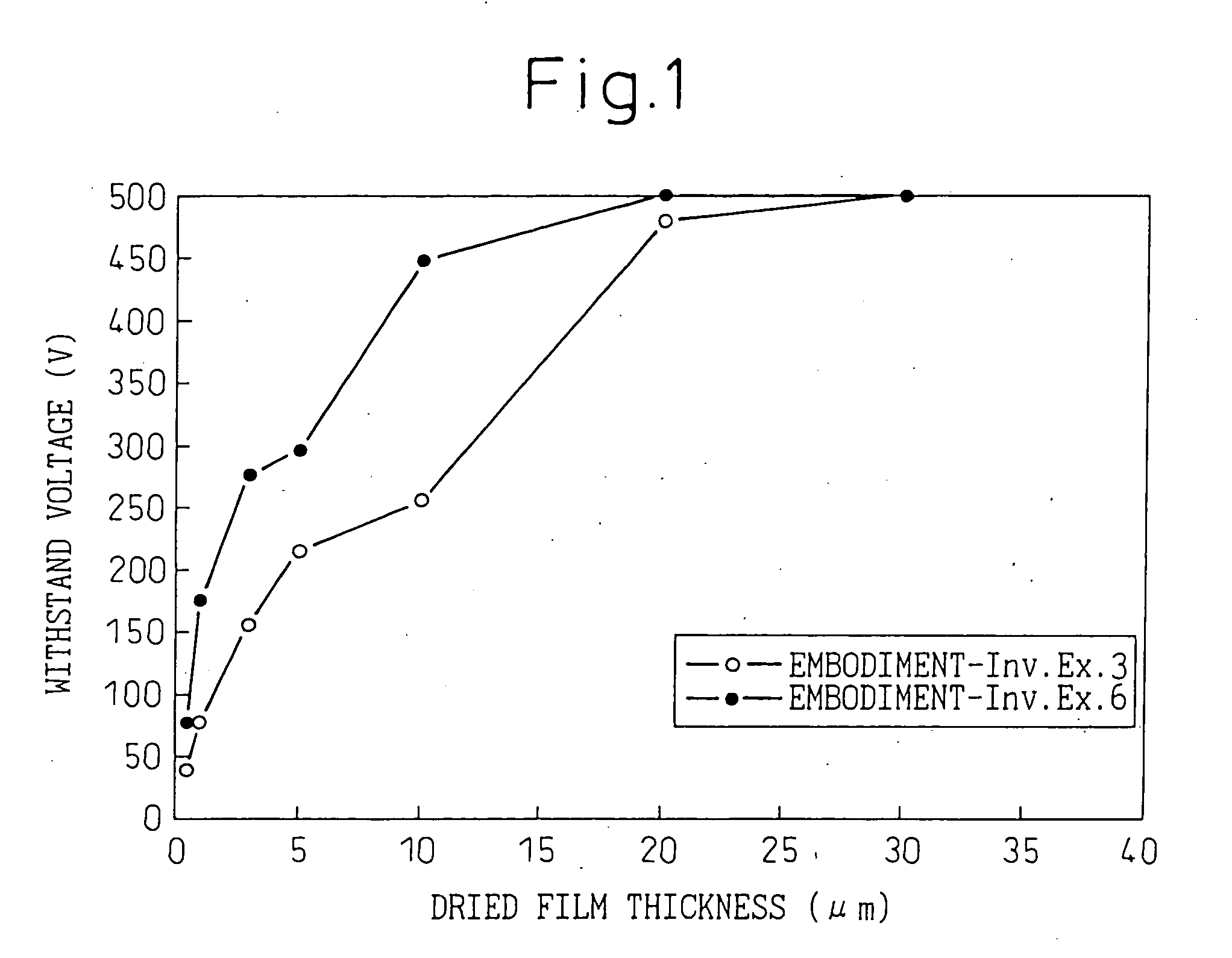
[0224] Each agent of the present invention of the pure silicone polymer compositions shown in Table 4 was used in the same way as in Example 1 to bake an insulation coating to give a film thickness after drying of 5 .mu.m on the surface of non-oriented magnetic steel sheet of a sheet thickness of 0.5 mm. Next, the steel sheet with this insulation coating was stacked, annealed at 400.degree. C..times.1 hr in the air, and examined as to the heat resistance of the coating. The results are shown in Table 4.
[0225] As a result of the tests, when treating sheets with solutions based on the pure silicone polymers of the present invention, in each case, a transparent lustrous coating state was maintained even after annealing at 400.degree. C. for 1 hour and no drop in adhesiveness or insulation could be observed. As opposed to this, in the case of an organic type varnish of the comparative material, a remarkable drop in the surface appearance, adhesiveness, and insulation occurred due to the...
example 3
[0226] A stator (armature) core treated on its surface using the present invention was used to prepare a microturbine generator. The stator core was obtained by punching from a magnetic steel sheet and calking and has bolt holes for fastening the core.
[0227] Next, the stator core was treated by Invention Example 1 of Example 1, the stator core was inserted into the case, then the core was bolted. In the past, since the core contacted the case or bolts and the calked layers contacted each other, a short-circuiting current flowed through the core, so the loss increased and there was a large temperature rise in the stator. If applying the present invention, it is possible to reduce and avoid the above short-circuiting current and possible to keep the temperature rise down to an average 3 degrees.
example 4
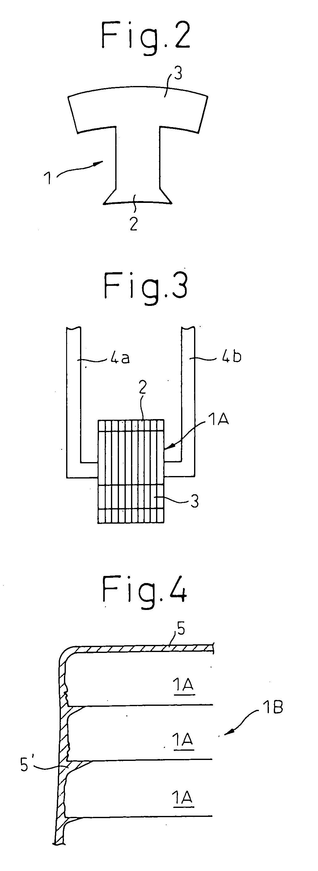
[0228] Cores treated on their end faces utilizing the present invention were combined to produce an XY linear motor. In this XY linear motor, since the flow of magnetic flux was three dimensional, cores punched out from ordinary magnetics steel sheet were combined at right angles.
[0229] Conventional cores contacted each other at their end faces, but insulation paper was sandwiched between the cores, so in the case of core contact, there was an increase in loss due to contact of the end faces and much variance in performance. On the other hand, if insulation paper was inserted, the clearance became relatively greater, the excitation current became greater, and an increase in the no-load resistance loss was caused.
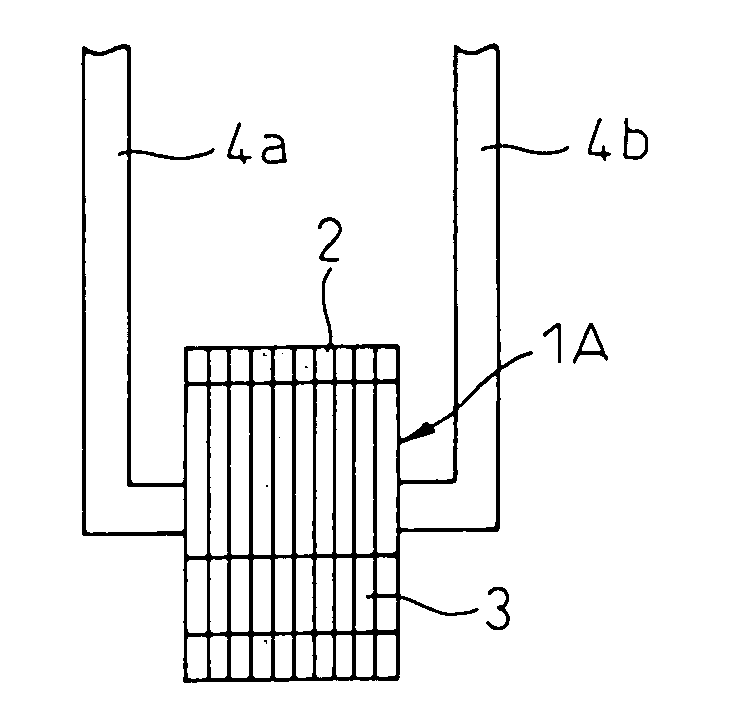
[0230] If the insulation treatment method of the present invention was used to treat the end faces of the U-shaped cores and two cores were combined, the loss was reduced and variance in performance was also reduced.
PUM
| Property | Measurement | Unit |
|---|---|---|
| Temperature | aaaaa | aaaaa |
| Fraction | aaaaa | aaaaa |
| Fraction | aaaaa | aaaaa |
Abstract
Description
Claims
Application Information
 - R&D
- Intellectual Property
- Life Sciences
- Materials
- Tech Scout
- Unparalleled Data Quality
- Higher Quality Content
- 60% Fewer Hallucinations
Browse by: Latest US Patents, China's latest patents, Technical Efficacy Thesaurus, Application Domain, Technology Topic, Popular Technical Reports.
© 2025 PatSnap. All rights reserved.Legal|Privacy policy|Modern Slavery Act Transparency Statement|Sitemap|About US| Contact US: help@patsnap.com


