Method of forming a ceramic coating on a substrate by electron-beam physical vapor deposition

a technology of electron beam and physical vapor deposition, which is applied in the direction of chemical vapor deposition coating, natural mineral layered products, machines/engines, etc., can solve the problems of not being able to make a single ceramic material coating, increasing the complexity of the physical deposition method, and high cost, so as to achieve accurate control

Inactive Publication Date: 2004-03-25
SN DETUDE & DE CONSTR DE MOTEURS DAVIATION S N E C M A
View PDF2 Cites 15 Cited by
  • Summary
  • Abstract
  • Description
  • Claims
  • Application Information

AI Technical Summary

Benefits of technology

0028] An object of the present invention is to enable a ceramic coating to be made having a composition gradient across its thickness, and to do so by using an EBPVD method in a single continuous deposition cycle without the method or the deposition installation being particularly complicated and with the composition of the various layers of the coating being accurately controlled.

Problems solved by technology

Nowadays, and even more in the future, the performance required of these ceramic coatings is such that they can no longer be made as a coating constituted by one layer of a single ceramic material.
Once the provision of multilayer ceramic coatings requires a plurality of deposition cycles to be performed using different sources, costs become very high.
Proposals have been made to provide ceramic coatings in a continuous stage, but at the price of making the physical deposition method more complex.
In spite of having different vapor pressures, it is not possible in practice to control the method in such a manner as to obtain a precise predetermined composition in each layer of the resulting coating.
In addition, it is difficult to make an ingot having inserts of different shapes as in EP 1 096 037.

Method used


Image

  • Method of forming a ceramic coating on a substrate by electron-beam physical vapor deposition
  • Method of forming a ceramic coating on a substrate by electron-beam physical vapor deposition
  • Method of forming a ceramic coating on a substrate by electron-beam physical vapor deposition

Examples


first embodiment

[0070] In a first embodiment, which is more particularly suitable for a bar whose composition varies stepwise, the ceramic powders constituting each layer are mixed separately.

[0071] The powders are mixed in a liquid medium, for example in water or in an organic solvent. An organic binder may be added to the resulting slip so as to facilitate subsequent pressing of the powders. The powder mixtures, possibly including binder, are subsequently dried.

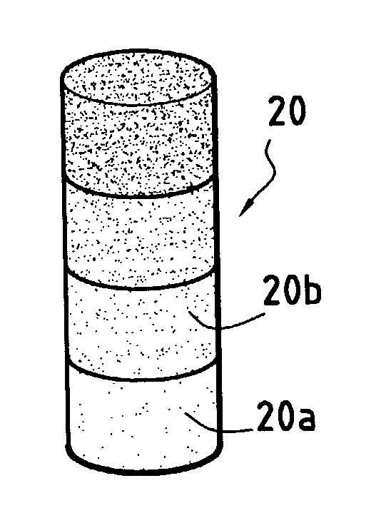
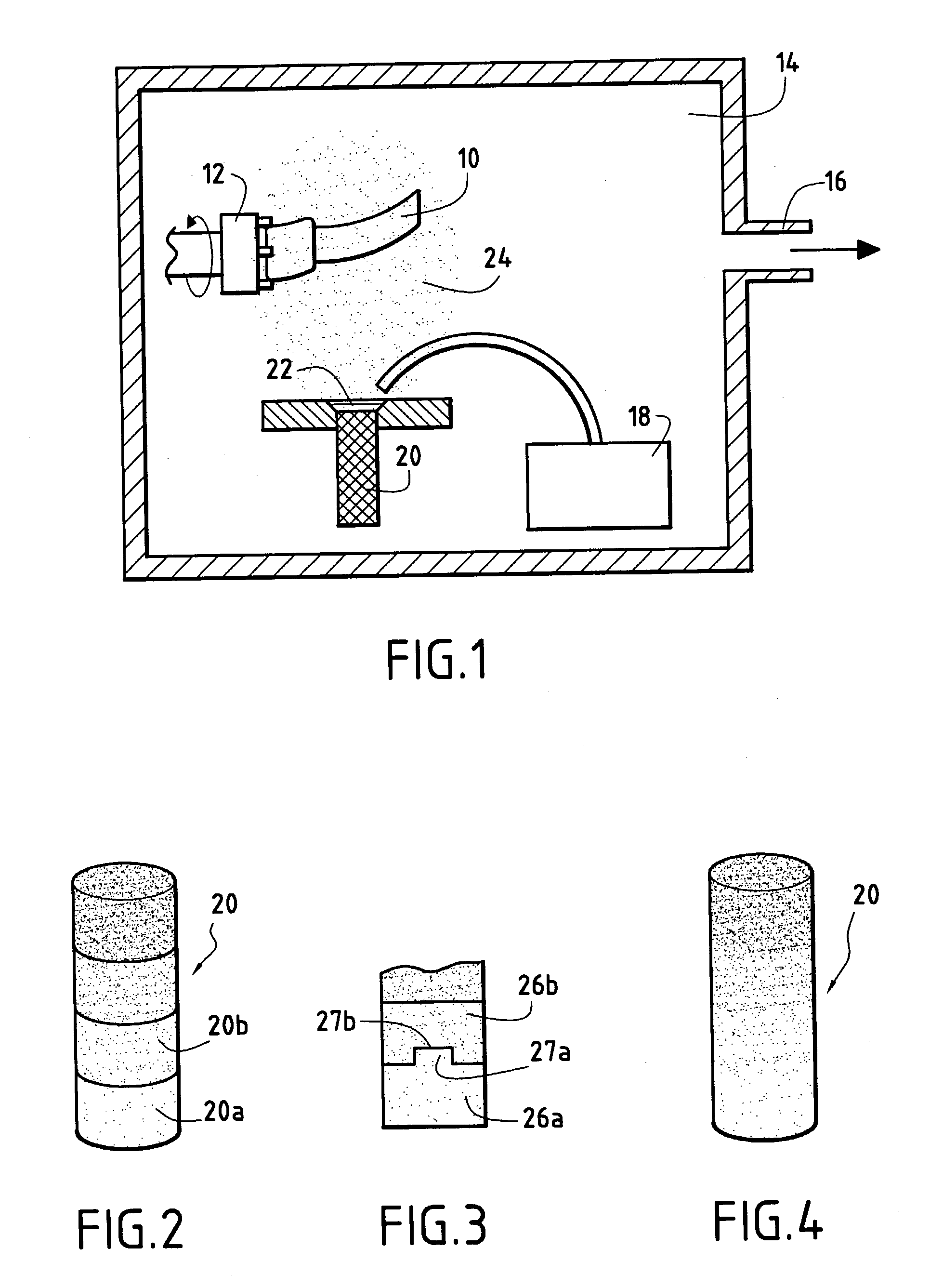
[0072] In the embodiment of FIG. 2, where the bar is made as a single piece, the compositions as prepared in this way for the various layers are introduced in the appropriate order into a mold having the form of the bar that is to be made.

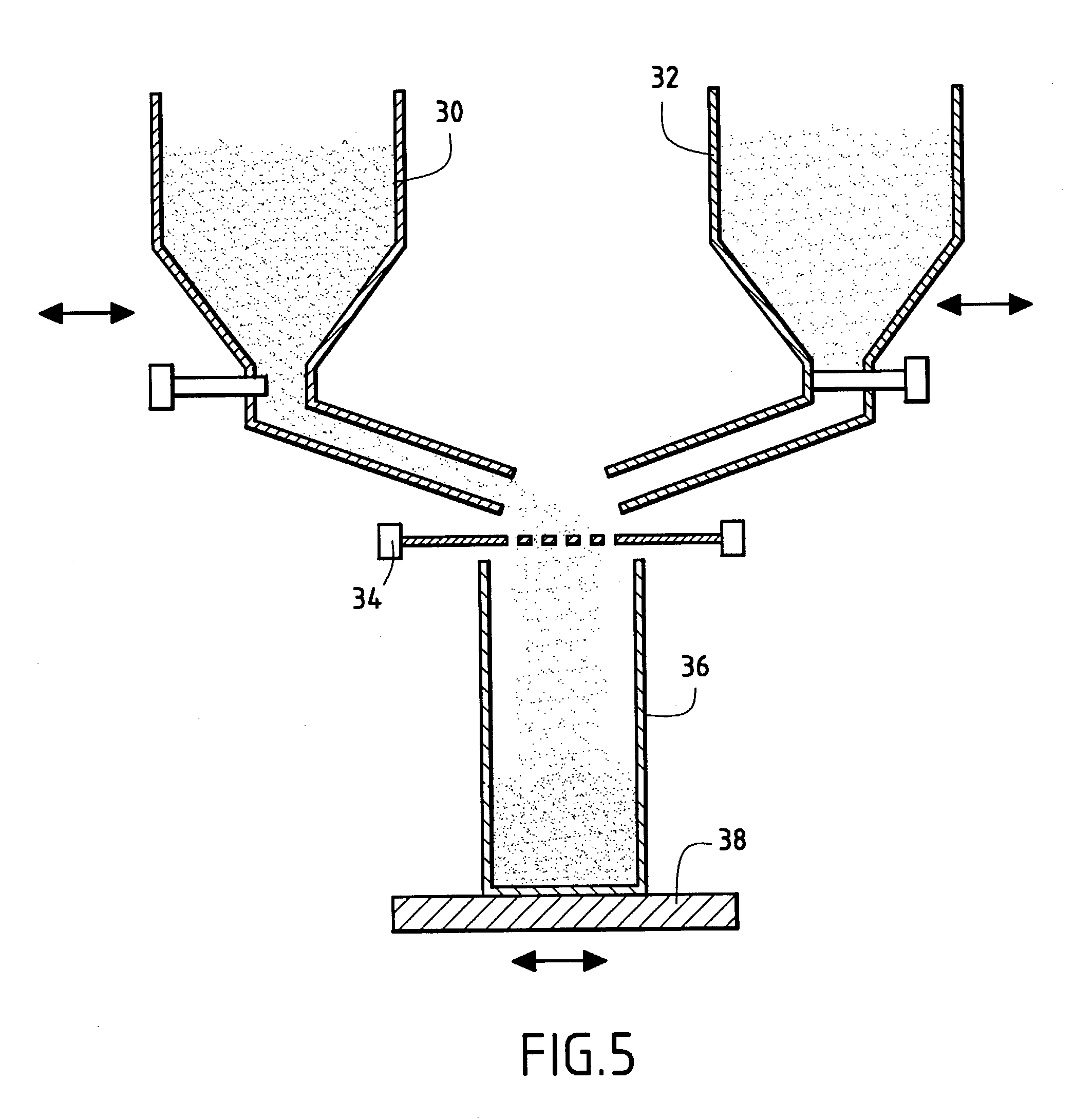
[0073] As shown in FIG. 5, these compositions may be stored in respective vibrating dispensers 30, 32 (only two are shown). The outlets from the dispensers are opened sequentially in the desired order. The powders pass through a grid or screen 34 and are received in the mold 36 which is carried on a vibra...

example 1

[0082] A bar made up of two distinct layers was made using an installation of the kind shown in FIG. 5.

[0083] A mixture of powders made up as follows was introduced into a first dispenser:

[0084] 93 grams (g) of zirconia powder ZrO.sub.2 and 7 g of yttrium oxide powder Y.sub.2O.sub.3 in the form of granules of size equal to about 150 micrometers (.mu.m) were mixed in an aqueous medium together with an organic binder; and

[0085] the mixture was dried.

[0086] A mixture of powders made as follows was introduced into a second dispenser:

[0087] 93 g of zirconia powder ZrO.sub.2, 7 g of yttrium oxide Y.sub.2O.sub.3, and 5.26 g of nickel oxide powder NiO in the form of granules of size equal to about 150 .mu.m were mixed in an aqueous medium together with an organic binder; and

[0088] the mixture was dried.

[0089] The powder mixture contained in the first dispenser was introduced initially into a cylindrical mold of circular section having a diameter of 50 millimeters (mm) and a height of 150 mm...

example 2

[0093] A bar comprising a composition that varied without steps was made by means of the installation of FIG. 6 by introducing the same mixtures as mentioned in Example 1 respectively in first and second dispensers, i.e. ZrO.sub.2+7% Y.sub.2O.sub.3 and ZrO.sub.2+7% Y.sub.2O.sub.3+5% NiO. A mold identical to that of Example 1 was filled as follows:

[0094] first dispenser set to maximum delivery rate for a length of time sufficient for obtaining a depth of powder in the mold equal to about 50 mm, the second dispenser being closed;

[0095] the first dispenser was closed progressively while the second dispenser was opened progressively so as to obtain a continuous composition gradient over a depth of about 60 mm in the mold; and

[0096] the second dispenser was fully opened and the first dispenser closed until the mold was completely full.

[0097] The powders in the mold were compacted by cold isostatic pressing at b 60 MPa and the powders were then baked at 1230.degree. C. for 60 min.

[0098] A...


PUM

PropertyMeasurementUnit
temperatureaaaaaaaaaa
pressureaaaaaaaaaa
sizeaaaaaaaaaa

Abstract

A composite target is placed in a chamber. The target is in the form of a bar made of ceramic powder and it presents composition that is not uniform in the longitudinal direction. At least one substrate is introduced into the chamber in order to have formed thereon a ceramic coating with a composition gradient. The top face of the bar is swept by an electron beam so as to melt the bar material at its top face and form a vapor cloud in the chamber under low pressure. A bar is used that presents a plurality of superposed layers of different compositions, with the composition within each layer being uniform over the entire cross-section of the bar. Each layer of the bar comprises zirconia and at least one oxide selected from the oxides of nickel, cobalt, iron, yttrium, hafnium, cerium, lanthanum, tantalum, niobium, scandium, samarium, gadolinium, dysprosium, ytterbium, and aluminum.

Description

[0001] The invention relates to forming ceramic coatings on substrates, and in particular to making bars or targets suitable for use as sources for forming such coatings by electron-beam physical vapor deposition.[0002] A particular field of application of the invention lies in forming outer ceramic coatings on thermal barriers for metal parts made of superalloys, such as blades or nozzles in gas turbines.[0003] In order to optimize the operation of gas turbines, in particular turbojets, it is desirable to make them operate at temperatures that are as high as possible, thereby increasing efficiency, reducing specific fuel consumption, and reducing polluting emissions (oxides of carbon, sulfur, nitrogen) and unburnt fuel.[0004] The parts of turbojets that are exposed to the highest temperatures, and in particular the turbine nozzles and blades, are usually made of refractory metal alloys, or superalloys, based on nickel or cobalt, and they are provided with protective coatings.[0005]...

Claims


Application Information

Patent Timeline
Patent Type & Authority Applications(United States)
IPC IPC(8): C04B35/488C23C14/02C23C14/06C23C14/08C23C14/24C23C14/30C23C14/54C23C28/04F01D5/28F02C7/00
CPCC04B35/486Y10T428/12C04B2235/3225C04B2235/3272C04B2235/604C04B2235/75C23C14/027C23C14/08C23C14/246C23C14/30C23C14/548F01D5/288F05D2230/90F05D2300/611C04B35/488
Inventor CHAPUT, CHRISTOPHEDELAGE, CYRILLEMALIE, ANDREPORTE, ISABELLESAINT-RAMOND, BERTRAND
Owner SN DETUDE & DE CONSTR DE MOTEURS DAVIATION S N E C M A
Why Eureka
Try Eureka