Colorimetric sensor
a colorimetric sensor and multi-layer technology, applied in the field of colorimetric sensors, can solve the problems of many of these systems having lifetime limitation problems and not being useful for simple visual indication
- Summary
- Abstract
- Description
- Claims
- Application Information
AI Technical Summary
Benefits of technology
Problems solved by technology
Method used
Image
Examples
example 1
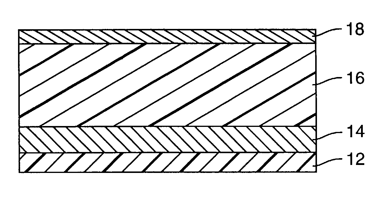
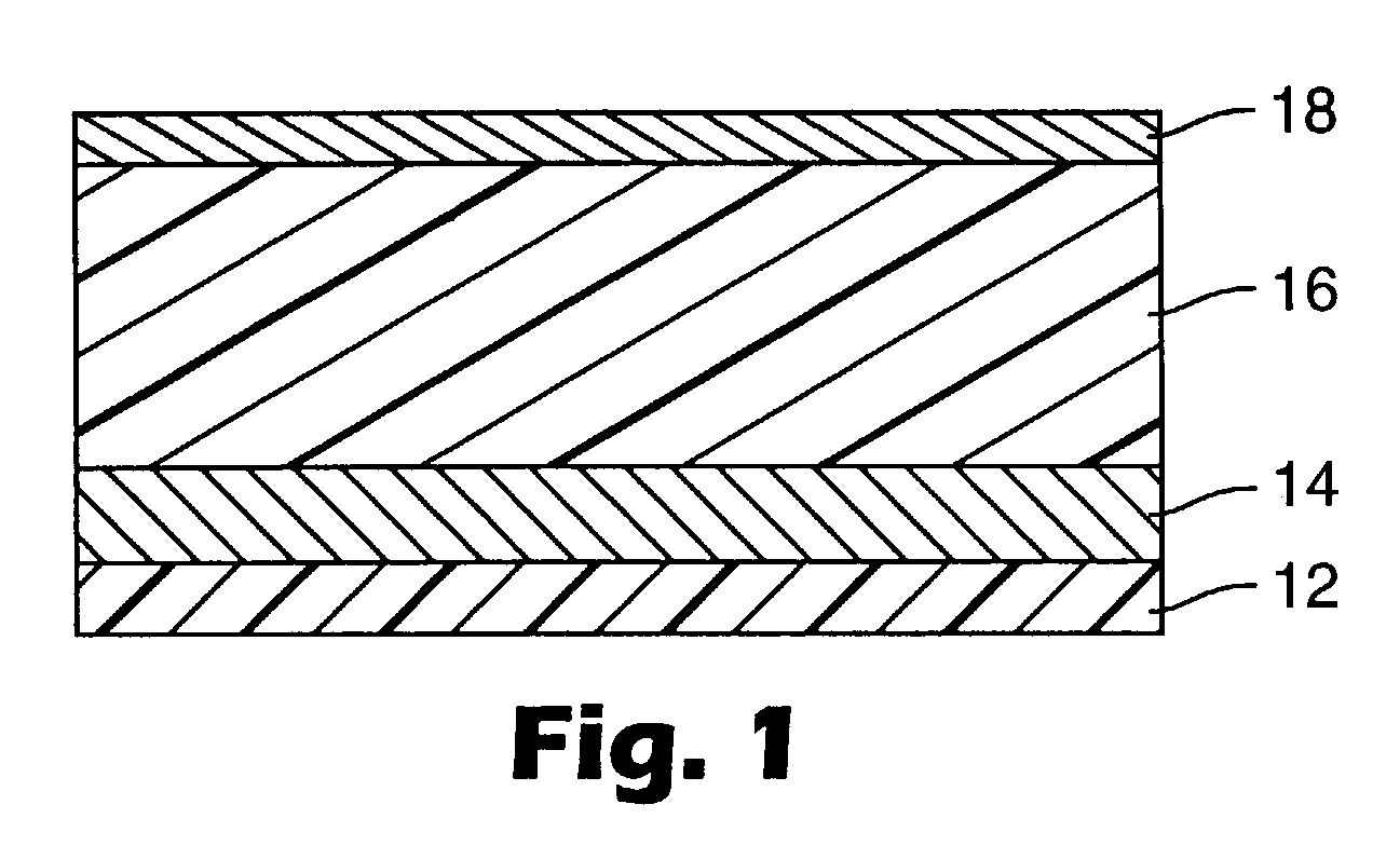
[0074] A multi-layered calorimetric sensor film was produced via the deposition method described in U.S. Pat. No. 5,877,895.
[0075] An aluminum reflective layer (100 nm) and polymeric detection layer (500 nm) were sequentially deposited upon a polyester substrate layer (50 .mu.m) in a single pass (15.24 m / min) through a vacuum web system. The aluminum reflective layer was thermally evaporated by feeding 0.1587 cm diameter aluminum wire (Alcoa stock number 1199, Pittsburgh, Pa.) onto an electrically heated (7V, 1250 amp) evaporation bar at a feed rate of 225 mm / min. The polymeric detection layer (500 nm) was deposited followed by an electron beam cure of 6.9 W-Sec. The monomer composition was a 48.5 / 48.5 / 3 by weight mixture of lauryl acrylate (available from Sartomer, Exton, Pa.) / IRR214 (a proprietary hydrocarbon diacrylate, available from UCB Chemicals, Drogenbos, Belgium) / Ebecryl170 (a phosphoric acid monoacrylate compound also available from UCB Chemicals). Chromium (Academy Precis...
example 2
[0077] Visible reflectance spectra were taken of the multi-layered films before and after exposure to a range of solvent vapors. Film sections (2.54 cm square, from Example 1) were affixed on glass slides and exposed to saturated organic vapors within sealed jars. Once equilibrated, the exposed films were removed and covered immediately with glass cover slides to prevent vapor desorption. Reflectance spectra of the exposed materials were then taken using a diffuse reflectance UV-VIS spectrometer. For all organic vapors tested, substantial red-shifting of the reflectance maxima were observed upon analyte exposure. The reflectance maximum centered at 524 nm (before exposure), for instance, exhibits shifts to higher wavelengths (red shifts). The magnitudes of the shifts ranged from 22 nm (acetonitrile) to 116 nm (methylene chloride), as shown in Table 2. This example shows that the multi-layered calorimetric sensor films respond to organic vapors, exhibiting calorimetric shifts for hal...
example 3
[0078] In an effort to gauge the response sensitivity to different analyte vapors, sensor film, made as described in Example 1, was exposed to analytes at a range of concentrations using a simple flow-through setup. Concentrations (as determined by partial pressures) were controlled by bath temperatures. Air was bubbled through neat liquid analytes, which were chilled using cold temperature baths to control the vapor pressure. Mixtures of solid carbon dioxide (dry ice) and 3-heptanone or ethylene glycol gave bath temperatures of -38.degree. C. and -15.degree. C. respectively. An ice water bath was used to give temperatures of 0.degree. C. Vapor pressures for each analyte were calculated at these temperatures using data from the Handbook of Vapor Pressure (Yaws, C. L. Gulf Publishing: Houston, 1994). Each air / vapor stream was then flowed via a stainless steel cannula into a septum-sealed vial containing the multi-layered film. The color changes of each film on exposure were monitored...
PUM
| Property | Measurement | Unit |
|---|---|---|
| visible light transmittance | aaaaa | aaaaa |
| thickness | aaaaa | aaaaa |
| thickness | aaaaa | aaaaa |
Abstract
Description
Claims
Application Information
 - R&D
- Intellectual Property
- Life Sciences
- Materials
- Tech Scout
- Unparalleled Data Quality
- Higher Quality Content
- 60% Fewer Hallucinations
Browse by: Latest US Patents, China's latest patents, Technical Efficacy Thesaurus, Application Domain, Technology Topic, Popular Technical Reports.
© 2025 PatSnap. All rights reserved.Legal|Privacy policy|Modern Slavery Act Transparency Statement|Sitemap|About US| Contact US: help@patsnap.com


