
Sliver type autonomous biosensors

a biosensor and sliver technology, applied in the field of in vivo or in vitro monitoring of biochemical species, can solve the problems of inability to monitor the site, inability to accurately detect the presence of bacteria, and poor usage compliance of patients

Inactive Publication Date: 2004-09-16
CASE WESTERN RESERVE UNIV
View PDF0 Cites 285 Cited by
  • Summary
  • Abstract
  • Description
  • Claims
  • Application Information

AI Technical Summary

Benefits of technology

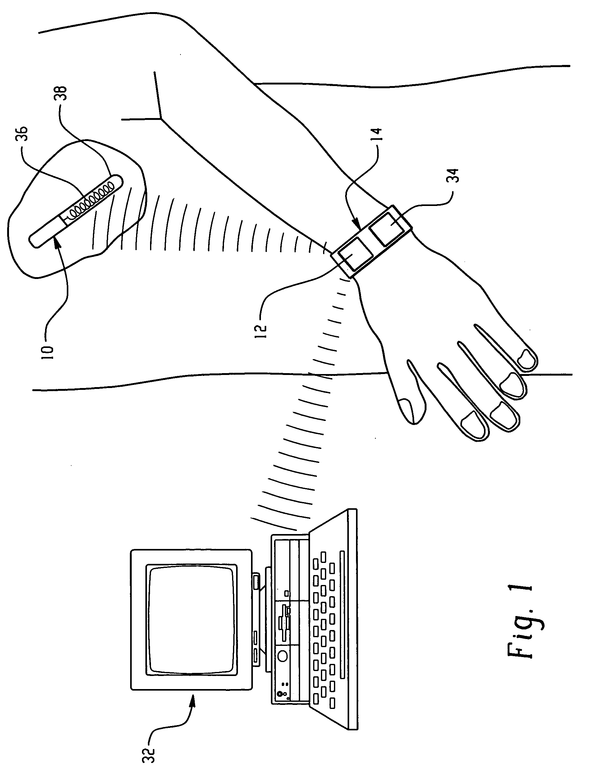
The present invention provides a sensor probe for detection of analytes in solution. The probe includes a sensing element that exhibits a detectable change in response to the analyte. The sensing element includes an immobilized optical sensing system comprising an enzyme, an ionophore, and a chromoionophore. The probe can simultaneously detect multiple analytes in a fluid. The method of forming the sensing element includes immobilizing an enzyme on a support material and then supporting a dye system on another support material. The sensor probe can remain in a patient's body for extended periods and minimizes safety hazards and risks associated with body movements. The combination of microsensing elements on a probe allows for simultaneous monitoring of enzyme substrates, antigens, ions, and temperature.

Problems solved by technology

Such systems tend to introduce technical inefficiencies and safety concerns that have often resulted in poor usage compliance by the patient and inaccuracies in the monitoring process.
There is also the potential for infection at the site or at the insertion point.
Further, there is a potential for the sensing elements, which sometimes contain hazardous or toxic materials, electrical wiring, or other parts of the probe device to break or to degrade within the patient.
This raises further safety concerns including the introduction of hazardous or toxic materials to the body and the potential for electric shocks.
These problems contribute to a psychological barrier to the use of currently available probes.

Method used


Image

  • Sliver type autonomous biosensors
  • Sliver type autonomous biosensors
  • Sliver type autonomous biosensors

Examples


example 1

Preparation of a Sliver-Type Glucose Probe

[0285] An optical glucose probe of the type shown in FIG. 8 is prepared as follows: A strip-shaped plastic plate 44 is covered with a CAP / CA membrane by a dipping method or spraying method. For example, 10 .mu.l of acetone solution containing 0.5 wt % of CA and 0.5 wt % of CAP is applied to a plastic plate and then allowed to stand until the acetone is evaporated. The resulting membrane is about 10.mu. in thickness. The membrane is treated with 1 ml of PBS solution containing 5 wt % of 1-ethyl-3-[3-(dimethylamino)propyl]carbodiimide hydrochloride (ECD-HCl) and 5 wt % of N-hydroxysuccinimide (NHS). It is then treated with a PBS solution containing 2 wt % of GOX and 0.5 wt % of a pH indicator dye (neutral red or congo red). The membrane is covered with a poly(acrylate) gel layer prepared by radical co-polymerization of sodium acrylate (10 wt %) and N,N'-methylenebis(acrylamide) (0.2 wt %). The acrylate layer is covered with a chitosan / heparin ...

example 2

Preparation of a Sliver-Type Glucose Probe

[0286] An optical glucose probe 400 as shown schematically in FIG. 24 is prepared as follows: A pH sensitive solvent polymeric membrane cocktail is prepared with a tetrahydrofuran (THF) solution containing 50 mg of poly-vinyl chloride (PVC), 100 mg of a membrane solvent (e.g., 2-nitrophenyl octyl ether), 0.5 mg of a hydrogen ion-selective chromoionophore (e.g., chromoionophore II (ETH 5350, 9-(diethylamino)-5-[(2-octyldecyl)imino]benzo[a]phenoxazine), 0.5 mg of a lipophilic anion-exchanger (e.g., KTpClPB (potassium tetrakis(4-chlorophenyl)borate)), and 5.6 mg of a potassium ionophore (e.g., bis(benzo-15-crown-5)(K.sup.+ ionophore, bis[(benzo-15-crown-5)-4'- -methyl]pimelate)). This cocktail is cast on a strip-shaped glass plate 44 and dried to form a first layer 410. The PVC membrane 410 thus obtained is covered with a CAP / CA membrane by the spraying method. The CAP / CA membrane is treated with a PBS solution containing ECD-HCl (5 wt %) and N...

example 3

Preparation of a Capsule-Type Glucose Probe

[0287] A glucose probe of the type shown in FIG. 16 is prepared as follows: A pH sensitive solvent membrane cocktail containing a hydrogen ion-selective chromoionophore (chromionophore III, , 1.6 mg of a lipophilic anion-exchanger (NaHFPB), 22 mg of a sodium ionophore (bis(12-crown-4) (Na.sup.+ ionophore, bis[(12-crown-4)methyl]2-dodecyl-2-- methylmalonate), and 100 mg of a membrane solvent (dioctyl sebacate) is prepared. Into 50 mg of the pH-sensitive membrane cocktail, 100 mg of ODS beads (average diameter: 25 .mu.m) are added and then stirred. CAP powder is treated with EDC-HCl and then NHS. After washing the ECD-treated CAP powder with water, the powder is treated with a PBS solution containing GOX. The powder is rinsed with a PBS solution and then dried in air. A polyurethane / CAP / CA tube 160 is prepared with 200 .mu.m diameter. The outermost layer 190 of the tube is made of polyurethane with about 10 .mu.m thickness and the inner layer...


PUM

PropertyMeasurementUnit
diameteraaaaaaaaaa
concentrationsaaaaaaaaaa
thicknessaaaaaaaaaa

Abstract

In vivo or in vitro monitoring of chemical and biochemical species (e.g., pH, or glucose levels) in the interstitial fluid of patients or in a sample of a fluid to be analyzed is provided by a probe (10, 70, 210, 270). For in vivo monitoring, the probe is readily inserted by a minimally invasive method. Optical or electrochemical sensing methods are employed to detect a physical or chemical change, such as pH, color, electrical potential, electric current, or the like, which is indicative of the concentration of the species or chemical property to be detected. Visual observation by the patient may be sufficient to monitor certain biochemicals (e.g., glucose) with this approach. A CAP membrane allows high enzyme loadings, and thus enables use of microminiature probes, and / or diagnosis of low levels of the analyte(s), with sufficient signal-to-noise ratio and low background current.

Description

BACKGROUND OF THE INVENTION[0001] This application claims the priority of U.S. Provisional Application Serial No. 60 / 501,066, filed Sep. 8, 2003, U.S. Provisional Application Serial No. 60 / 444,582, filed Feb. 3, 2003, and U.S. Provisional Application Serial No. 60 / 417,971, filed Oct. 11, 2002, the specifications of which are incorporated herein in their entireties by reference.[0002] 1. Field of the Invention[0003] The present invention relates to in vivo or in vitro monitoring of a biochemical species. It finds particular application in the monitoring of glucose in diabetics, lactate monitoring for those undergoing physical exercise and heart monitoring for those suffering from heart conditions, oxygen monitoring, and the like, and will be described with particular reference thereto. It will be appreciated, however, that the invention has a variety of other applications, both for clinical monitoring and for research purposes.[0004] 2. Discussion of the Art[0005] There are numerous ...

Claims


Application Information

Patent Timeline
Patent Type & Authority Applications(United States)
IPC IPC(8): A61B5/00C12Q1/00
CPCA61B5/14528A61B5/14532A61B5/14539A61B5/14546C12Q1/001A61B5/1459A61B5/14865A61B5/686A61B5/1455
Inventor GRATZL, MIKLOSTOHDA, KOJIYANG, JIANROZAKIS, GEORGE
Owner CASE WESTERN RESERVE UNIV
Learn More