Process for separating and recovering valuable metals

a technology for valuable metals and separating processes, applied in chemical/physical processes, niobium compounds, combustible gas purification/modification, etc., can solve the problems of large amount of various kinds of by-products, complicated steps, and environmental pollution, and achieve the effect of increasing the deposit degree of ammonium metavanadate, increasing the leaching speed, and reducing the amount of by-products

Inactive Publication Date: 2004-10-28
Y K YSK TECHNOSYST
View PDF4 Cites 31 Cited by
  • Summary
  • Abstract
  • Description
  • Claims
  • Application Information

AI Technical Summary

Benefits of technology

0015] Furthermore, in the above-described first step making use of the ammonia-containing leaching water, it is economical to carry out leaching under an atmosphere in the presence of oxygen as described in claim 6, particularly in the presence of an oxygen-containing gas, preferably by blowing air or the like into the leaching device. Additionally, the leaching temperature is 50.degree. C. or higher. Preferably, making the temperature be from 70 to 100.degree. C. further increases the leaching speed, which allows the reaction to efficiently proceed.
0016] In the process for separating and

Problems solved by technology

Direct dumping of such a waste catalyst not only causes environmental pollution, but also associates with the waste of valuable metals, and thus petroleum refining companies contract with disposal dealers to deal with waste catalysts.
However, the use of sulfuric acid for neutralizing the caustic soda solution results in generating a large amount of Grauber's salt (sodium sulfate) as a by-product and also in leaving the sodium salt to the final stage.
Furthermore, this method also poses a problem that makes all of the steps complicated, the steps including requirement of a variety of treating che

Method used


Image

  • Process for separating and recovering valuable metals

Examples


Embodiment Construction

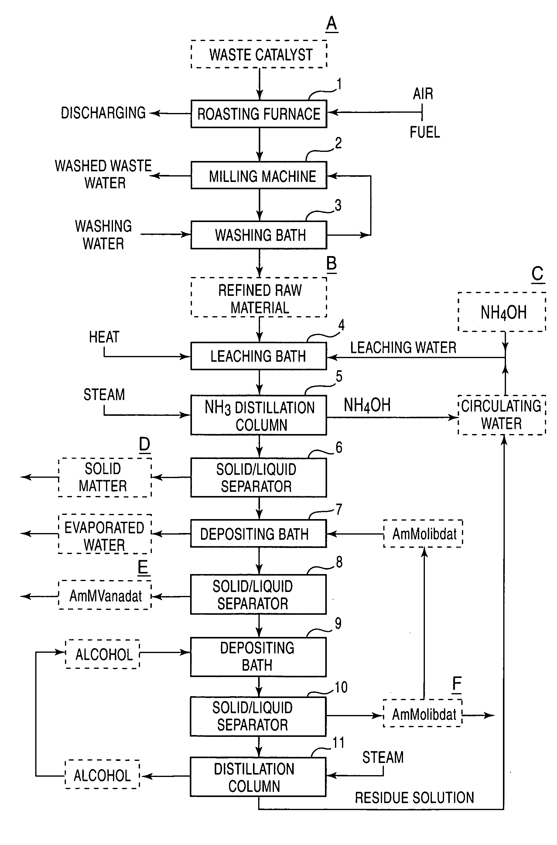
[0033] Hereafter, a process for separating and recovering valuable metals of the present invention will be set forth in detail with reference to an Example. In addition, the present invention is by no means limited due to this Example, and can be carried out, as appropriate, with modifications within the spirit of the present invention.

[0034] A waste catalyst used in desulfurization treatment of petroleum was spread on a heat resistant wire gauze and was heated with a gas burner to burning remove oil matter and sulfur stuck to the waste catalyst. Then, the resultant catalyst was transferred into a rotary tube electric furnace having a diameter of 10 cm and a length of 90 cm and was oxidation roasted at 600.degree. C. for three hours while ventilating. Further, the resulting material was subjected to grinding with a dry DESINTA type grinder followed by water washing. The pretreated waste catalyst thus prepared had metal components contents of 7.2% vanadium, 4.9% molybdenum, 2.9% nick...


PUM

PropertyMeasurementUnit
Angleaaaaaaaaaa
Percent by massaaaaaaaaaa

Abstract

The present invention provides a process for economically separating and recovering valuable metal components, with no many kinds of chemicals being used, with no waste water that causes environmental pollution being discharged, and also perfectly no by-products being formed by means of simple steps. The present invention includes a step of leaching a raw material containing at least vanadium oxides and molybdenum oxides with ammonia-containing leaching water to obtain a leached solution containing a vanadium compound and a molybdenum compound, a step of adding ammonium orthomolybdate to the leached solution to separate and recover the deposited ammonium metavanadate from a first solution for separation, a step of adding a water-soluble alcohol to the separated solution to separate and recover the deposited ammonium orthomolybdate from a second solution for separation, a step of distilling the second solution for separation to separate and recover the water-soluble alcohol and a residue-solution, a step of adding at least a portion of the residue solution to the ammonia-containing leaching water as the portion thereof, and a step of returning a portion of the recovered ammonium orthomolybdate and a total of a recovered, water-soluble alcohol to the system for reusing.

Description

[0001] 1. Field of the Invention[0002] The present invention relates to a process for separating and recovering valuable metals, and particularly to a process for separating and recovering valuable metals contained in waste catalysts used in hydrodesulfurization of petroleum products, etc., with no many kinds of chemicals being used, with waste water that causes environmental pollution being minimally discharged, and also with perfectly no by-products being formed by means of simple steps.[0003] 2. Description of the Related Art[0004] Materials produced by supporting molybdenum / cobalt-based catalyst metals on alumina-based carriers are normally used as desulfurization catalysts for petroleum products. Use of this catalyst, for example, for the desulfurization of heavy oil causes heavy metals such as vanadium, nickel and the like, contained in the heavy oil, to adhere to the catalyst, as well as gradually lowering the activity of the catalyst on account of iron, sulfur, phosphorous, ...

Claims


Application Information

Patent Timeline
IPC IPC(8): C22B3/14C22B3/44C22B7/00C22B34/22C22B34/32C22B34/34
CPCC22B3/0002C22B3/44C22B34/22C22B34/34C22B3/14Y02P10/20
Inventor AKAHOSHI, TOSHIAKI
Owner Y K YSK TECHNOSYST
Why Eureka
Try Eureka