Composite material having high thermal conductivity and low thermal expansion coefficient, and heat-dissipating substrate, and their production methods

Inactive Publication Date: 2004-12-02
HITACHI METALS LTD
View PDF9 Cites 45 Cited by
  • Summary
  • Abstract
  • Description
  • Claims
  • Application Information

AI Technical Summary

Benefits of technology

0108] The plating layer is preferably Ni--P, Ni--B, Cu, etc. When the impregnating metal is copper or its alloy, requiring a heat resistance of 700.degree. C. or higher, the Ni--B plating is particularly preferable because it is less diffusion-reactive to the metal and thus stable. The metal layer may be utilized not only for sealing, but also as a primer for adhesion to other parts. Such metal layer desirably improves the adhesion to heat-generating bodies such as semiconductor devices and packages.
0109] Because the heat-dissipating substrate comprising aluminum or its alloy as an impregnating metal has a large thermal conductivity, a thermal expansion coefficient close to those of silicon and compound semiconductors, and good solderability, it is suitable for heat spreaders, etc. for semiconductor devices using soldering for bonding. In addition, because the graphite/aluminum composite material has low melt-forging temperature and heat-treating temperature, it is advantageous in low production cost. Because the heat-dissipating substrate of the present invention has a thermal expansion coefficient closer to those of semiconductor devices and is lighter

Problems solved by technology

However, substrates made of these composite materials are disadvantageously poor in workability because of containing ceramics.
Though composite material substrates made of metals having small thermal expansion coefficients such as tungsten or molybdenum and copper have also been proposed, these composite material substrates are disadvantageously poor in workability.
Despite the above advantages, these carbon-based metal composite materials are disadvantageous in having much larger thermal expansion coefficients than those of silicon and compound semiconductors.
Large differences from silicon and compound semiconductors in a thermal expansion coefficient undesirably exert large thermal stress to CPUs or light-emitting diodes during soldering or brazing heat-dissipating substrates to the CPUs or the light-emitting diod

Method used


Image

  • Composite material having high thermal conductivity and low thermal expansion coefficient, and heat-dissipating substrate, and their production methods
  • Composite material having high thermal conductivity and low thermal expansion coefficient, and heat-dissipating substrate, and their production methods
  • Composite material having high thermal conductivity and low thermal expansion coefficient, and heat-dissipating substrate, and their production methods

Examples


example 2

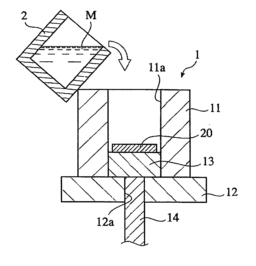
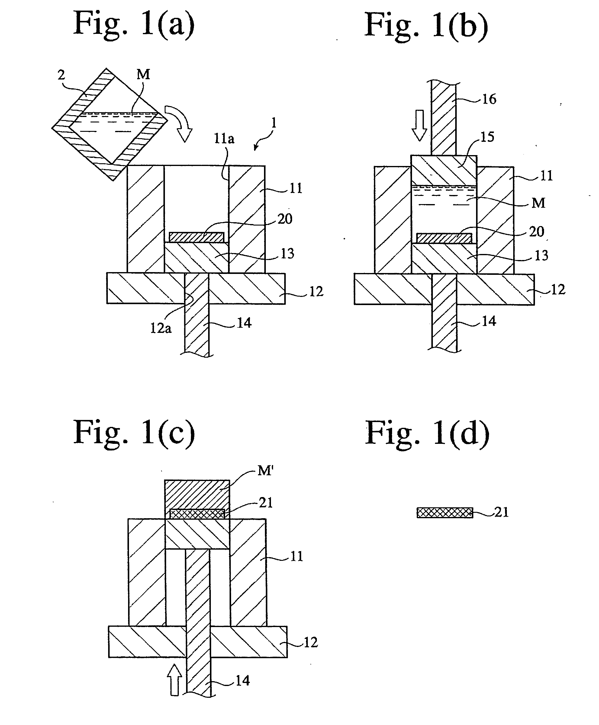
[0131] Using the same porous graphitized extrudate as in Example 1 and pure copper (purity 99.9% or more), a graphite / copper composite material was produced as follows. After a melt (1350.degree. C.) of the above pure copper poured into a cavity of the die apparatus (held at 1000.degree. C.) shown in FIG. 1(a), in which the above porous graphitized extrudate was placed, an upper punch was lowered to conduct melt-forging at 100 MPa for 5 minutes. Excess pure copper was cut away to obtain the graphite / copper composite material. This graphite / copper composite material was subjected to a heat treatment under the following conditions.

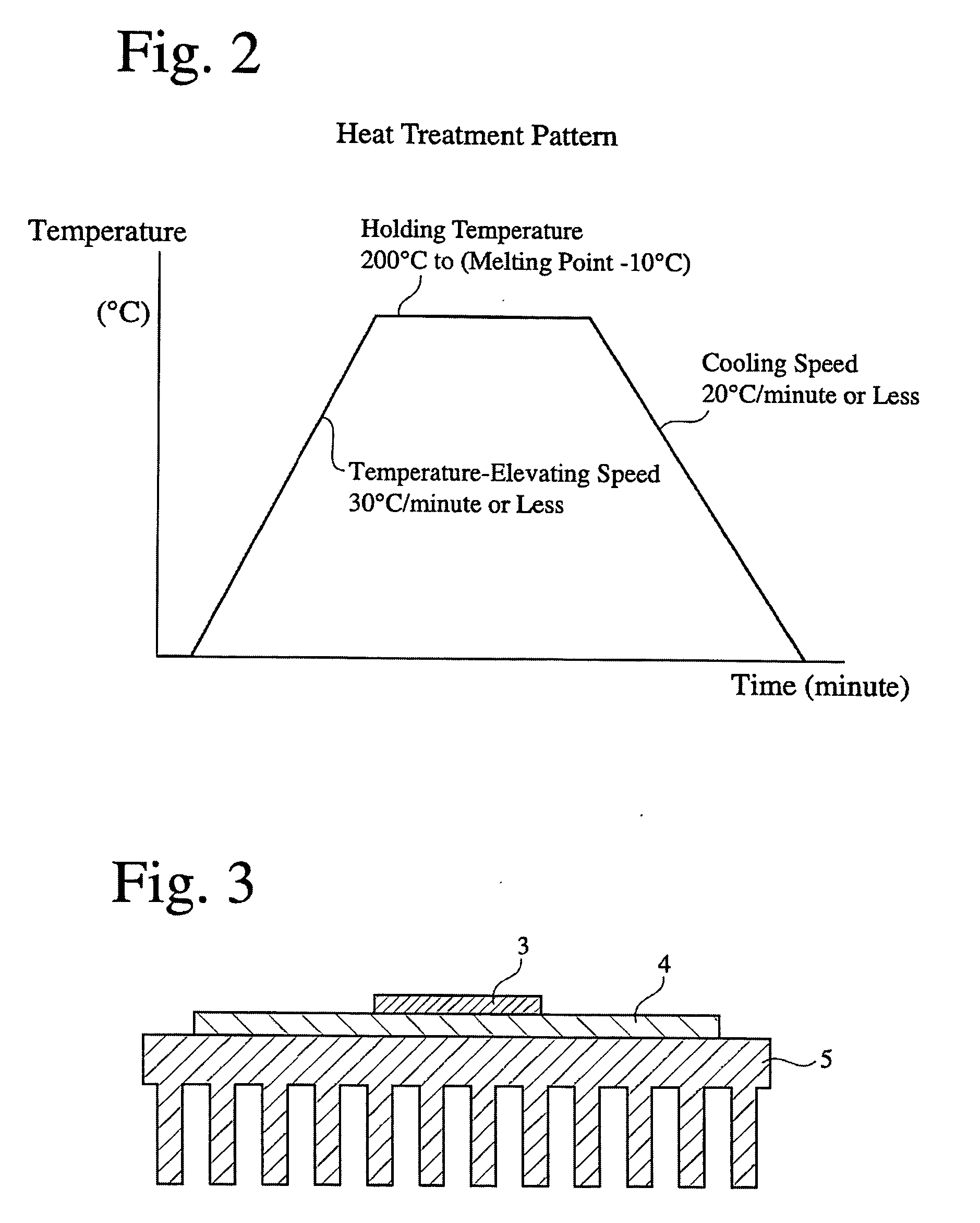
9 Temperature-elevating speed: 5.degree. C. / minute, Holding conditions: 900.degree. C. .times. 120 minutes, and Cooling speed: 5.degree. C. / minute.

[0132] The graphite / copper composite material after the heat treatment was cut to a size of 40.0 mm.times.20.0 mm.times.2.0 mm to provide a heat-dissipating substrate sample. The thickness direction of the heat-di...

example 3

[0137] Using the same porous graphitized extrudate as in Example 1 having a specific bulk density of 1.70, an ash content of 0.3% by mass, resistivity of 5.0 .mu..OMEGA.m and 8.5 .mu..OMEGA.m, respectively, in an extrusion direction and in the direction perpendicular to the extrusion direction, a thermal expansion coefficient of 0.6.times.10.sup.-6 / K and 2.0.times.10.sup.-6 / K, respectively, in an extrusion direction and in the direction perpendicular to the extrusion direction, and a thermal conductivity of 230 W / mK and 120 W / mK, respectively, in an extrusion direction and in the direction perpendicular to the extrusion direction, and brass comprising 70% by mass of Cu and 30% by mass of Zn, a graphite / brass composite material was produced under the following conditions.

[0138] After a melt (1350.degree. C.) of the above brass was poured into a cavity of the die apparatus (held at 1000.degree. C.) shown in FIG. 1(a), in which the above graphite was placed, an upper punch was lowered ...

example 4

[0142] A heat-dissipating substrate of 40.0 mm.times.20.0 mm.times.2.0 mm cut out from the graphite / Al--Si alloy composite material (after the heat treatment) of Example 1 shown in Table 6 was subjected to electroless Ni--P plating after a zincate treatment. A heat-dissipating substrate of 40.0 mm.times.20.0 mm.times.2.0 mm cut out from the graphite / Cu composite material (after the heat treatment) of Example 2 shown in Table 7 was also subjected to electroless Ni--B plating. To evaluate the correlation of the presence of a plating layer and sealability, the amount of a helium gas passing through each plated heat-dissipating substrate was measured by a helium leak detector DLMS-33 available from ULVAC, Inc. according to JIS C 7021 A-6. The amount of a helium gas passing through the plated heat-dissipating substrate, as the amount of a leaked helium gas, was used as a parameter of sealability. The results are shown in Table 9 below.

14TABLE 9 Amount of Leaked Type of Thickness Helium G...


PUM

PropertyMeasurementUnit
Fractionaaaaaaaaaa
Fractionaaaaaaaaaa
Linear densityaaaaaaaaaa

Abstract

A composite material having a high thermal conductivity and a small thermal expansion coefficient, which is obtained by impregnating a porous graphitized extrudate with a metal; the composite material having such anisotropy that the thermal conductivity and the thermal expansion coefficient are 250 W/mK or more and less than 4x10<-6>/K, respectively, in an extrusion direction; and that the thermal conductivity and the thermal expansion coefficient are 150 W/mK or more and 10x10<-6>/K or less, respectively, in a direction perpendicular to the extrusion direction.

Description

[0001] The present invention relates to a composite material having a high thermal conductivity and a small thermal expansion coefficient, a heat-dissipating substrate formed therefrom, and methods for producing them, particularly to a composite material composed of a porous graphitized extrudate and aluminum or copper and thus having a high thermal conductivity, a small thermal expansion coefficient and small resistivity with substantially no thermal hysteresis, which is suitable for heat sinks for electronic equipment, etc., a heat-dissipating substrate such as a heat sink, etc. formed from such composite material, and methods for producing them.[0002] Because electronic parts have been increasing their heat generation as their integration, volume, output, etc. are increasing, demand is mounting on materials having a high thermal conductivity and a small thermal expansion coefficient. Because semiconductor devices such as CPUs, light-emitting diodes, etc. generate large amounts of...

Claims


Application Information

Patent Timeline
IPC IPC(8): C04B41/45C04B41/52C04B41/81C04B41/89C22C1/10H01L21/48H01L23/373
CPCC04B41/009Y10T428/12493C04B41/52C04B41/81C04B41/89C04B2111/00844C22C1/1036C22C47/06C22C2001/1021H01L21/4878H01L23/373H01L23/3733H01L23/3736C04B41/4523Y10T428/30H01L2924/0002C04B41/0072C04B41/4521C04B41/5096C04B41/5155C04B41/5127C04B41/515C04B41/5116C04B41/51C04B41/4541C04B41/5144C04B35/522C04B38/00H01L2924/00Y10T428/249957Y10T428/249967Y10T428/249969Y10T428/31678Y10T428/24997C22C1/1021
Inventor FUKUSHIMA, HIDEKO
Owner HITACHI METALS LTD
Why Eureka
Try Eureka