Laser illumination system
a laser illumination and laser technology, applied in the field of laser apparatus configuration, can solve the problems of not being able to hold such information, using a cw laser, and not being able to achieve improvement at a temperature lower, etc., and achieves the effects of small off-current, large mobility, and large mobility
- Summary
- Abstract
- Description
- Claims
- Application Information
AI Technical Summary
Benefits of technology
Problems solved by technology
Method used
Image
Examples
embodiment 1
[0048] Embodiment 1
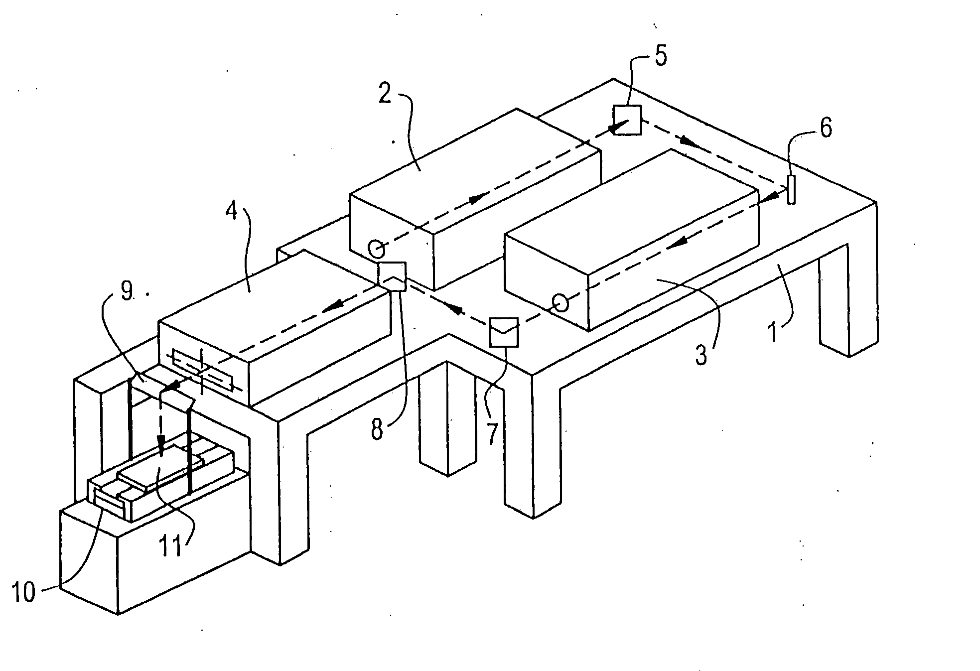
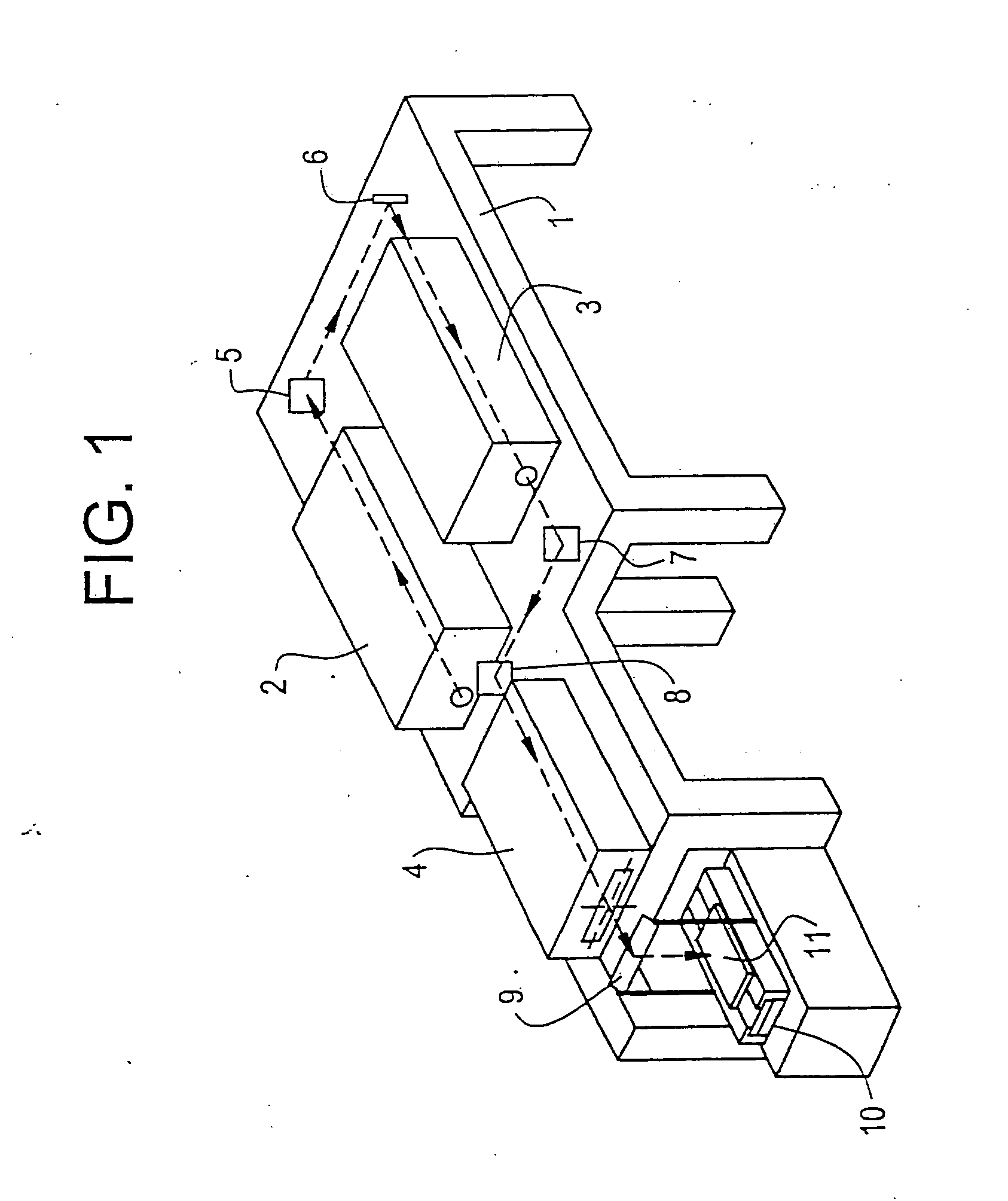
[0049] First of all, a description will be made of an apparatus. FIG. 1 shows the concept of a laser annealing apparatus used in this embodiment. Reference numeral 1 denotes a main body of the laser annealing apparatus. An oscillator 2 emits KrF excimer laser light (wavelength: 248 nm; pulse width: 25 ns). Apparently other excimer lasers and other types of laser may also be used.
[0050] Laser light emitted from the oscillator 2 is reflected by full-reflection mirrors 5 and 6, amplified by an amplifier 3, reflected by full-reflection mirrors 7 and 8, and introduced into an optics 4. Although not shown in FIG. 4, an energy attenuating device is inserted between the mirror 8 and the optics 4. FIG. 3 shows the configuration of the energy attenuating device.
[0051] As shown in FIG. 3, the energy attenuating device is of a type in which a single plate of filter faces a traveling laser beam and the energy transmission factor is changed by changing the angle formed by the...
embodiment 2
[0058] Embodiment 2
[0059] Although the mirror G being partially transmissive. provides the advantage of real-time measurement of the laser light illumination energy (first embodiment; FIG. 1), it has a disadvantage that part of the laser energy is lost. This embodiment is directed to an apparatus for solving that problem. However, the apparatus of this embodiment cannot measure the energy of the linear laser beam on a real-time basis.
[0060]FIG. 5 shows a laser light illuminating portion of the apparatus of this embodiment. A mirror P in FIG. 5 corresponds to the mirror G in FIG. 1. The mirror P is a full-reflection mirror, and a 4%-reflection mirror Q is disposed under the mirror P. An energy component reflected by the mirror Q enters a beam profiler R. The mirror Q is smaller than the mirror P, because the beam profiler measures a small area each time. The mirror Q moves in link with the beam profiler R, and is adapted to slide over a range longer than the linear laser beam. Durin...
embodiment 3
[0061] Embodiment 3
[0062] We have studied the method for improving the crystallinity of an amorphous or crystalline silicon or silicon compound film by illuminating it with laser light and, in particular, the manufacturing method of a film suitable as a material for a liquid crystal display device, and propose the following apparatus that facilitates manufacture of such a film.
[0063] As in the first embodiment, this embodiment uses the laser annealing apparatus shown in FIG. 1. An energy attenuating device is inserted into the output-side optical path of the optics 4 of FIG. 1. FIG. 6 shows the configuration of the energy attenuating device. A brief description will be made of the mechanism of this device. Referring to FIG. 6, the light attenuation factor of each of special light attenuation filters 104 and 105 is changed by changing the angle formed by the laser beam and the filter. The transmission factor of each of the light attenuation filters 104 and 105 is maximum when the fi...
PUM
| Property | Measurement | Unit |
|---|---|---|
| temperature | aaaaa | aaaaa |
| temperature | aaaaa | aaaaa |
| wavelength | aaaaa | aaaaa |
Abstract
Description
Claims
Application Information
 - R&D
- Intellectual Property
- Life Sciences
- Materials
- Tech Scout
- Unparalleled Data Quality
- Higher Quality Content
- 60% Fewer Hallucinations
Browse by: Latest US Patents, China's latest patents, Technical Efficacy Thesaurus, Application Domain, Technology Topic, Popular Technical Reports.
© 2025 PatSnap. All rights reserved.Legal|Privacy policy|Modern Slavery Act Transparency Statement|Sitemap|About US| Contact US: help@patsnap.com


