Gas sensor and manufacturing method thereof

a technology of gas sensor and manufacturing method, which is applied in the direction of instruments, coatings, material analysis, etc., can solve the problems of headache, dizziness, sickness, headache, nausea, etc., and achieve the effects of high sensitivity, rapid recovery rate, and good repeatability

Inactive Publication Date: 2005-03-03
IND TECH RES INST
View PDF5 Cites 35 Cited by
  • Summary
  • Abstract
  • Description
  • Claims
  • Application Information

AI Technical Summary

Benefits of technology

[0017] It is therefore a primary object of the present invention to provide a gas sensor with high sensitivity, good repeatability and rapid recovery rate at room temperature. The gas sensor of the present invention solves the problems of conventional semiconductor metal oxide gas sensors that require heat desorption of the gas chemically absorbed on the oxide layer. In addition, the sensor of the present invention is economic in preparation.

Problems solved by technology

These toxic gases are colorless and tasteless and cannot be easily detected by human senses.
When the concentration of toxic gases in an environment exceeds an allowable range, symptoms of headache, dizziness, sickness, or even shock or death can result.
These gas analysis instruments have the advantages of high accuracy, high sensitivity, and low detection limit; however, their application is limited due to a large profile with low portability, high power consumption, structural complexity, and high cost.
These gas sensors are applicable at room temperature, however, they have a short lifetime due to the corrosive property of the liquid electrolyte.
In addition, calibration of the sensor baseline is required since chemical buildup at the reference electrode may cause baseline drift.
Moreover, electrochemical gas sensors are usually costly.
However, heat desorption of the absorbed gases at 200 to 500° C. is required, and the sensitivity of the sensor is not satisfactory.
High throughput production cannot be easily achieved due to the requirement of vacuum equipment; the thermal treatment also increases the cost; in addition, the working temperature of the sensor is 200-500° C.
The process is complicated and costly due to noble metals and multiple heat treatments.
In addition, the gas sensor cannot be used at room temperature.
This preparation is costly due to the heat treatment, and the gas sensor also needs to be used at 280-400° C.
This gas sensor is costly and has to be used at 180-400° C.
The drawbacks of these gas sensors include low sensitivity, selectivity, and stability with gas.
Longtime operation at high temperatures may, however, causes irreversible changes in the electrical properties of metal oxides, leading to signal drift.
The heating requirement of these gas sensors also evokes several problems such as increased size of the gas sensor, power consumption, and temperature control.
Therefore, the cost of the gas sensor cannot be reduced.
The sensor detects CH4 and C3H8 at a lower temperature, such as 150° C. for CH4 and 190° C. for C3H8; however, ion beam sputtering and Pt or Pd electrodes are costly, and the working temperature cannot be reduced to room temperature.
However, the sensor still cannot be used at room temperature.
The above mentioned sensors have a common problem-unable to be used at room temperature; therefore, researchers are focusing on the study of a sensor with low working temperature.
The disadvantage of the sensor is the difficulty of controlling sensor temperature since the temperature of the sensor is increased by lightening time.
In addition, the design for light induction is complicated and the cost cannot be reduced.

Method used


Image

  • Gas sensor and manufacturing method thereof
  • Gas sensor and manufacturing method thereof
  • Gas sensor and manufacturing method thereof

Examples


example 1

Gas sensor of the Present Invention and Preparation Thereof

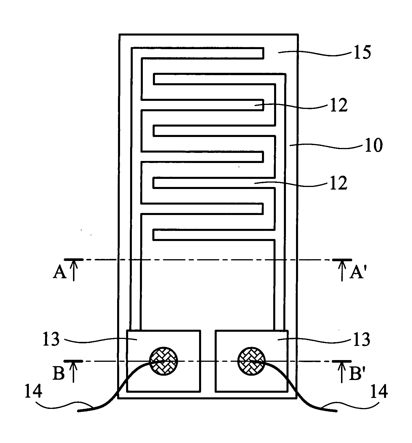
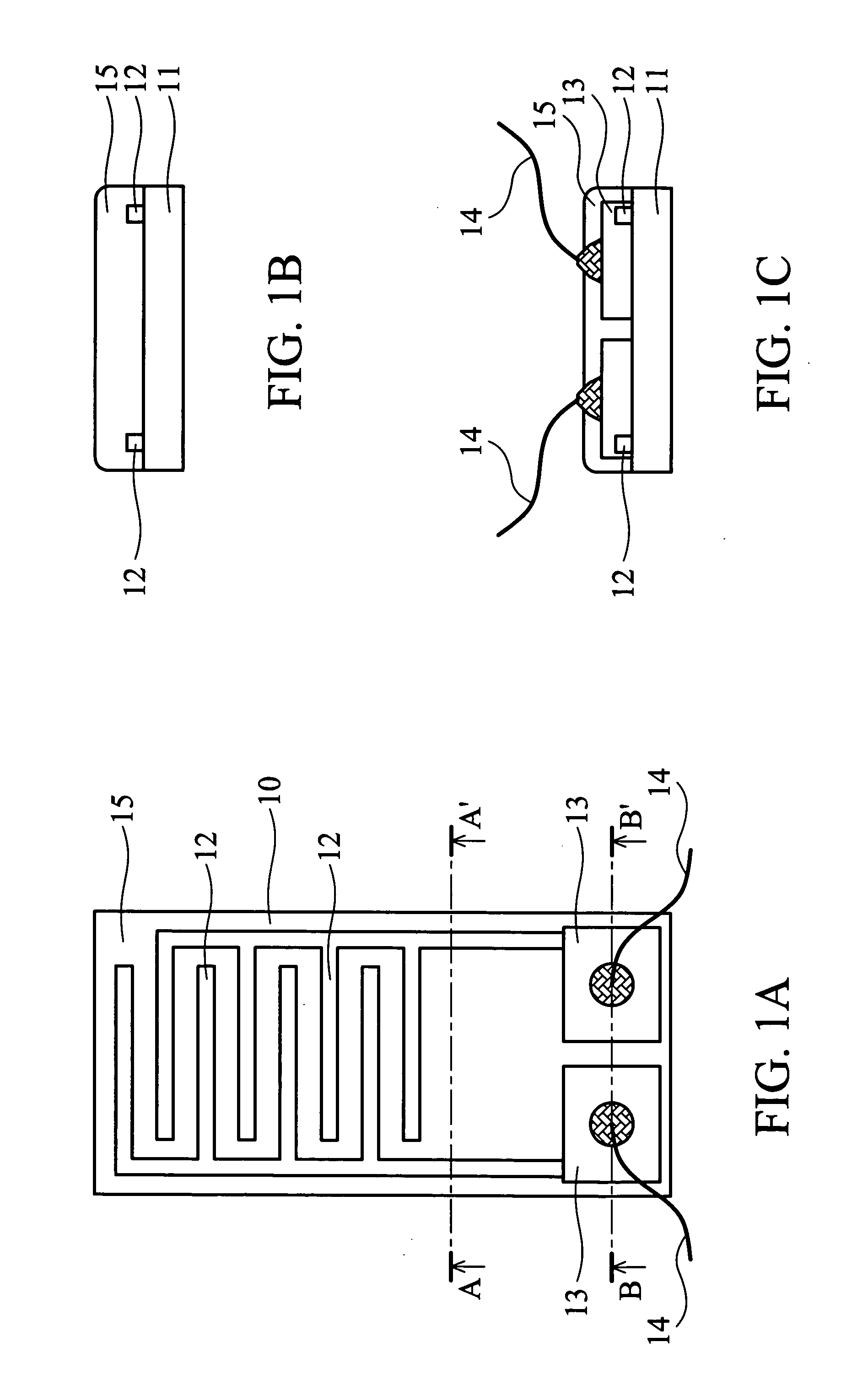
[0036] As shown in FIG. 1A, the gas sensor 10 of the present invention comprises an aluminum oxide ceramic substrate 11 (10×5 mm), with a pair of comb-shaped, gold electrodes 12 thereon. The electrodes do not contact each other. An Ag / Pd layer 13 is coated at the end of the electrodes 12. The gold electrodes 12 and the Ag / Pd layer 13 are formed by screen printing. A SnO2 gas sensing film 15 covers the gold electrode 12.

[0037] First, tin (II) 2-ethylhexanoate was dissolved in 2-ethylhexanoic acid to form an organo-metallic solution at weight percentage 10%. One mg of the single-walled carbon nanotubes (Carbon Nanotechnology Inc., prepared by HiPco process) and 10 g of the organo-metallic solution were mixed. The mixture was vibrated by ultrasonic oscillator for 2 hours to evenly distribute the carbon nanotubes in the solution and form a suspension containing carbon nanotubes. The suspension was then applied to the gold elec...

example 2

Preparation of a Conventional Gas Sensor

[0038] The conventional gas sensor does not contain carbon nanotubes. Preparation of the conventional gas sensor follows:

[0039] Tin (II) 2-ethylhexazoate was dissolved in 2-ethylhexanoic acid to form an organo-metallic solution at weight percentage 10%. The organo-metallic solution was applied to gold electrodes 12 and Ag / Pd layer 13 as shown in FIG. 1. The substrate covered with the solution was then dried at 150° C. for 30 minutes to evaporate the solvent. After that, the substrate was heated in a furnace for half hour with air circulation to dissolve the organo-metallic solution at 500° C., and a microcrystalline and porous SnO2 gas sensing film was formed at a thickness of 5-10 μm.

example 3

Comparison of the Gas Sensors of the Present Invention and the Conventional Gas Sensor

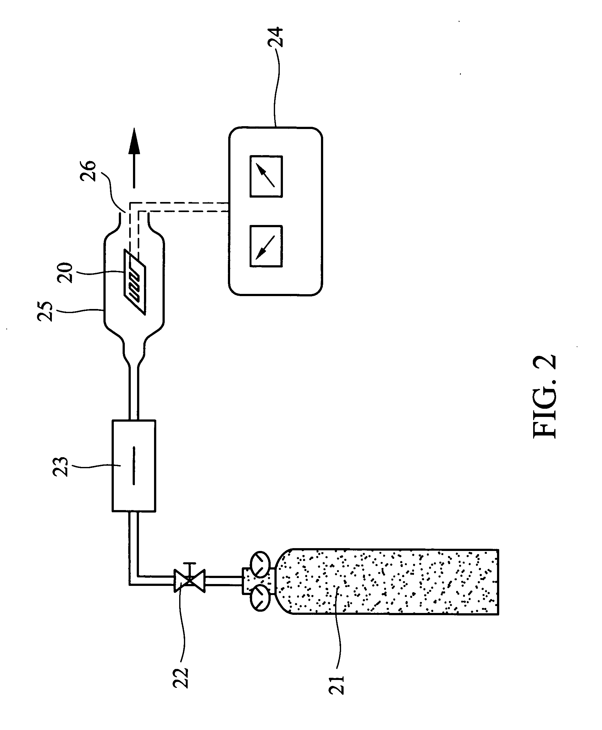
[0040] The schematic diagram of the gas detection apparatus in the experiment is shown in FIG. 2. Before testing, the gas sensing film 15 on the Ag / Pd layer 13 as shown in FIG. 1 was scraped and signal lines 14 were soldered to the Ag / Pd layer 13. The gas sensor 20 of the present invention as shown in FIG. 2 was placed in a glass chamber 25. The input of 1010 ppm NO2 gas 21 was controlled by an intake valve 22 and a mass flow controller 23 100 mL / min. The resistor changes were recorded by LCR meter 24. The outlet of the gas flow is shown as 26 in FIG. 2, with results shown in FIG. 3 and 4.

[0041]FIG. 3 and 4 respectively compare the characteristic curves of the gas sensor of the present invention and the conventional SnO2 gas sensor to 1010 ppm NO2 gas. The coordinates in FIG. 3 and 4 are the same, with mark 1 indicating initialized the input of NO2 and mark 2 stoppage. The right upper plate of FI...


PUM

PropertyMeasurementUnit
temperatureaaaaaaaaaa
temperaturesaaaaaaaaaa

Abstract

A gas sensor and manufacturing method thereof. The gas sensor includes a substrate, a pair of electrodes disposed on the substrate, and a gas sensing thin film covering the electrodes, the gas sensing thin film is made up of carbon nanotubes and tin oxide.

Description

BACKGROUND OF THE INVENTION [0001] 1. Field of the Invention [0002] The present invention relates to a gas sensor and manufacturing method thereof. More particularly, the present invention relates to a gas sensor using carbon nanotubes and metal oxide as a sensing film. [0003] 2. Description of the Related Arts [0004] Naturally occurring gases such as carbon monoxide (CO), nitrogen oxides (NOx), hydrogen sulfide (H2S), or methane (CH4) can be hazardous to humans. These toxic gases are colorless and tasteless and cannot be easily detected by human senses. When the concentration of toxic gases in an environment exceeds an allowable range, symptoms of headache, dizziness, sickness, or even shock or death can result. Gas analyzers provide real-time monitoring of gas content in airtight or unventilated environments, providing timely notification when the concentration of toxic gases exceeds a threshold. [0005] Atomic / molecular absorption spectrometry, atomic / molecular fluorescence spectr...

Claims


Application Information

Patent Timeline
Patent Type & Authority Applications(United States)
IPC IPC(8): G01N7/04G01N27/00
CPCB82Y30/00G01N7/04G01N27/127G01N2291/0257G01N29/036
Inventor WEI, BEE-YULAI, HONG-JENSU, PI-GUEYWU, REN-JANGLIN, HONG-MINGSUN, YI-LU
Owner IND TECH RES INST
Why Eureka
Try Eureka