Low NOx combustion using cogenerated oxygen and nitrogen streams

Inactive Publication Date: 2005-03-17
PRAXAIR TECH INC
View PDF16 Cites 31 Cited by
  • Summary
  • Abstract
  • Description
  • Claims
  • Application Information

AI Technical Summary

Benefits of technology

[0036] This embodiment of the invention preferably involves the process steps of injecting coal into a boiler, supplying less than the total required air flow to the boiler via combustion air. The remaining air required for combustion is sent to an air separation plant where it is divided into its components: an oxygen-rich stream, and a nitrogen-rich by-product stream. The oxygen-rich stream is injected near the coal feed point into the fuel rich flame zone in the boiler to minimize fuel NOx formation, and the nitroge

Problems solved by technology

Since sufficient air velocities must be provided to mix fuel and air within the furnace space to complete combustion, it is difficult to create a very large fuel rich zone to provide a long enough residence time for maximum NOx reduction.
Although the LNB is a fairly inexpensive way to reduce NOx and many advancements have been made in the burner design, currently available versions are not yet capable to reach the emissions limits in pending regulations of 0.15 lb (as NO2) per MMBtu of coal fired for utility boilers.
However, the volume of the flue gas is increased by FGR, which causes a higher pressure drop and a greater heat transfer in the convective section and limits the maximum amount of FGR allowed for a give boiler.
Furthermore, handling recycled flue gas is very maintenance intensive.
Depending on where the flue gas is extracted from the system, it may contain fly ash and/or sulfuric acid vapors which would make it corrosive to recycling equipment.
In addition, it will have residual levels of heat and typically low pressures which require larger pipes to handle the flow rates and may have higher than desired oxygen levels depending on the infiltration of air into the flue system and the overall stoichiometry of the boiler operation.
The dirty nature of the gas also makes measurement and control difficult; and when systems break down, they are expensive to fix so repairs are not always done.
In addition, any off-spec operation of the boiler (e.g. high CO levels) can bring these undesirable contaminants back into the boiler house, creating operator safety issues should leaks develop or process safety issues should combustible gases be present in the recycled stream.
These tests were single particle combustion tests p

Method used


Image

  • Low NOx combustion using cogenerated oxygen and nitrogen streams
  • Low NOx combustion using cogenerated oxygen and nitrogen streams
  • Low NOx combustion using cogenerated oxygen and nitrogen streams

Examples


Embodiment Construction

[0056] The invention will be described with reference to the Figures, although a description that refers to the Figures is not intended to limit the scope of that which is considered to be the present invention.

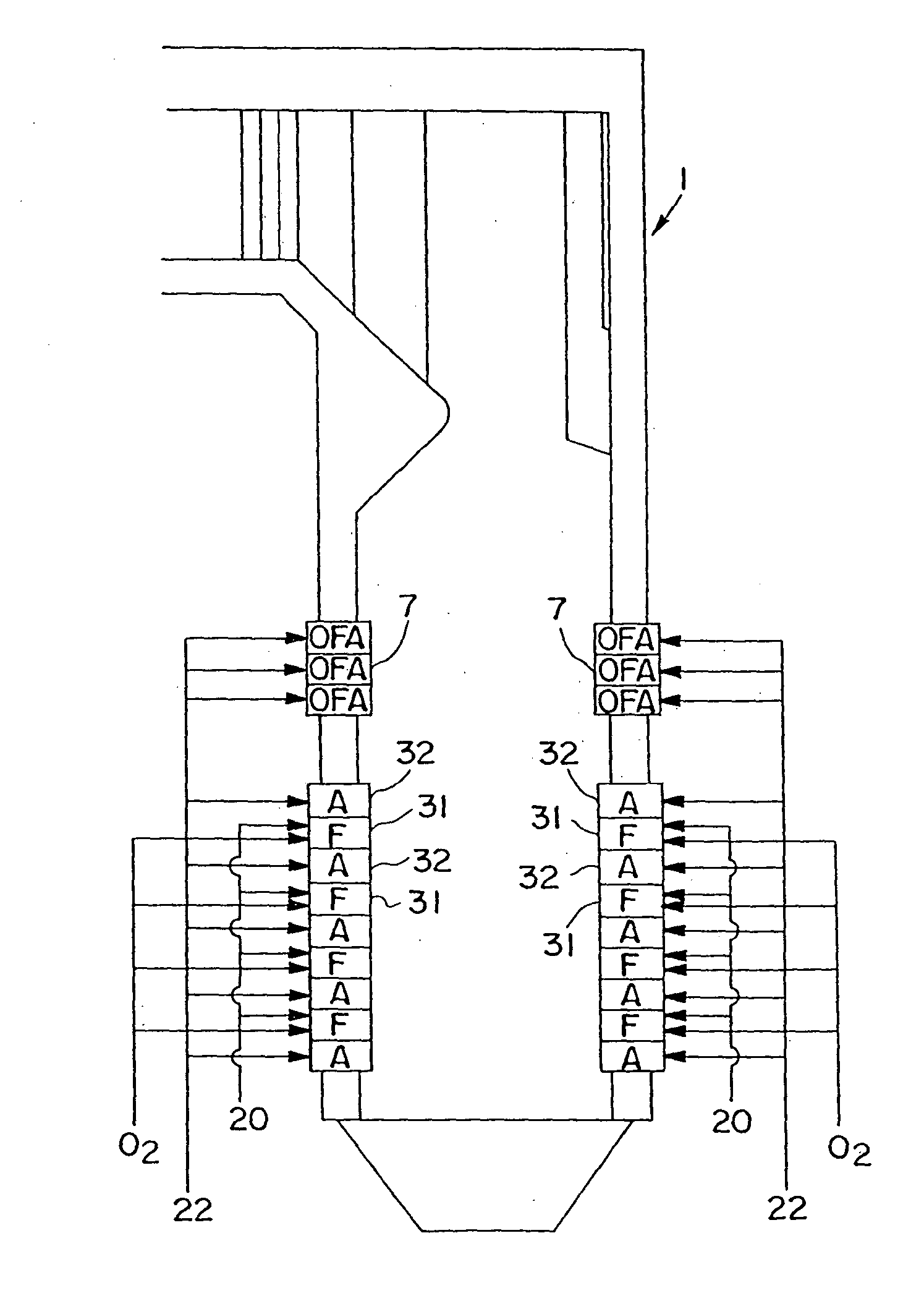
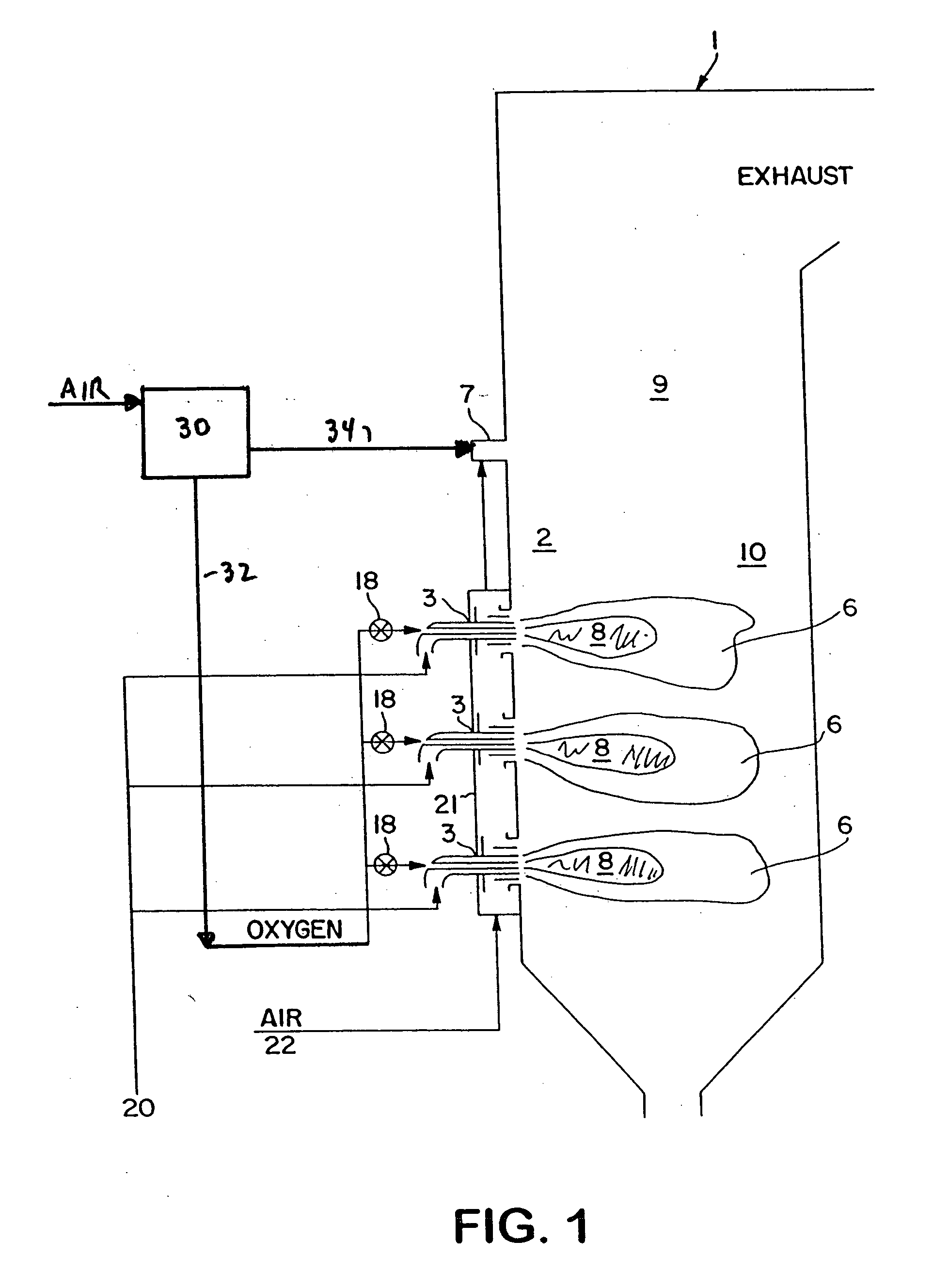
[0057]FIG. 1 shows combustion device 1, which can be any apparatus wherein combustion is carried out in the interior 2 of the device. Preferred combustion devices include furnaces and boilers which are used to generate steam to generate electric power by conventional means, not shown. Combustion in the combustion device produces flue gas which leaves the combustion device via a stack at the top.

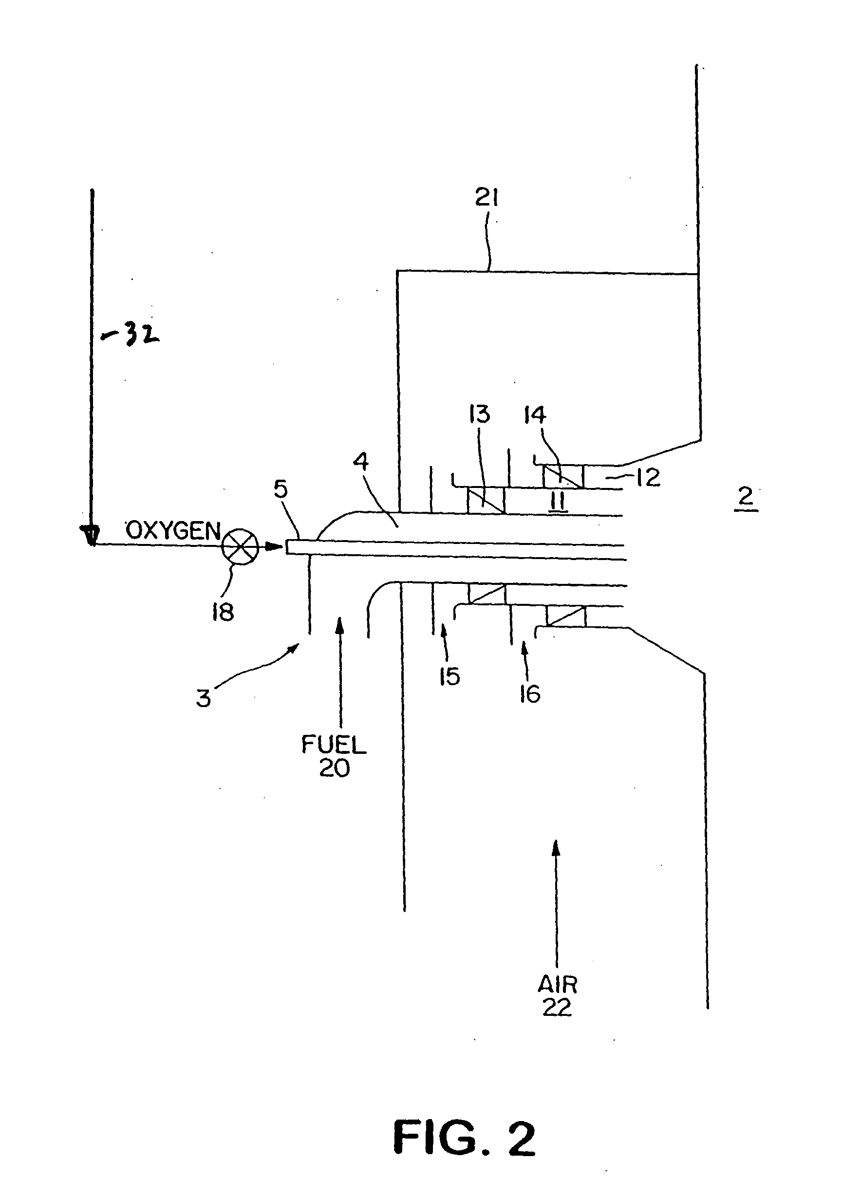
[0058] Each burner 3 in a sidewall or end wall of combustion device 1 feeds fuel, air and oxygen from sources thereof outside the combustion device 1 into the interior 2 of combustion device 1. Suitable fuels include hydrocarbon liquids, such as fuel oil, and also include pulverulent hydrocarbon solids, a preferred example of which is pulverized coal or petroleum coke.

[0059] As seen...


PUM


Abstract

Combustion of hydrocarbon fuel is achieved with less formation of NOx by feeding the fuel into a slightly oxygen-enriched atmosphere, and separating air into oxygen-rich and nitrogen-rich streams which are fed separately into the combustion device.

Description

[0001] This invention was made with United States Government support under Cooperative Agreement No. DE-FC26-00NT40756 awarded by the Department of Energy. The United States Government has certain rights in the invention.FIELD OF THE INVENTION [0002] The present invention relates to combustion of hydrocarbon fuels containing bound nitrogen, particularly of coal. BACKGROUND OF THE INVENTION [0003] Environmental awareness is growing in the U.S. and around the world leading to increasing public and regulatory pressures to reduce pollutant emissions from boilers, incinerators, and furnaces. One pollutant of particular concern is NOx (by which is meant oxides of nitrogen such as but not limited to NO, NO2, NO3, N2O, N2O3, N2O4, N3O4, and mixtures thereof), which has been implicated in acid rain, ground level ozone, and fine particulate formation. [0004] A number of technologies are available to reduce NOx emissions. These technologies can be divided into two major classes, primary and se...

Claims


Application Information

Patent Timeline
IPC IPC(8): F23D14/32F23C5/32F23C9/08F23C99/00F23D1/00F23D14/22F23L7/00
CPCF23C5/32F23C9/08F23C2900/07021F23C2900/99004Y02E20/344F23L7/00F23L2900/07002F23L2900/07005F23L2900/07008F23D1/00Y02E20/34F23D14/22F23D14/32
Inventor KOBAYASHI, HISASHIBOOL, LAWRENCE E.SNYDER, WILLIAM J.
Owner PRAXAIR TECH INC
Why Eureka
Try Eureka