Biosensor

a biosensor and sensor technology, applied in the field of biosensors, can solve the problems of destroying hemocytes captured in the filter, and unable to measure whole blood itsel

Inactive Publication Date: 2005-04-07
PANASONIC CORP
View PDF22 Cites 108 Cited by
  • Summary
  • Abstract
  • Description
  • Claims
  • Application Information

AI Technical Summary

Benefits of technology

[0059] It is also preferable that the first filter and / or the second filter contain a reagent for suppressing a reaction between oxidoreductase and cholesterol contained in any of high density lipoprotein, low density lipoprotein and very low density lipoprotein in the sample solution.

Problems solved by technology

However, the surfactant, as being included in the reaction system, has an adverse effect on hemocytes, making it impossible to measure whole blood itself, as done in the glucose sensor.
When the filter is inappropriately incorporated in the sensor, however, hemocytes captured in the filter are destroyed and hemoglobin dissolves out.
As the hemocytes are destroyed and become small components of about the size of the hemoglobin, it becomes difficult to filter such small components with the filter.
Hence the hemoglobin flows into the sample solution supply pathway, which may cause a measurement error.
This is presumably caused by the fact that a difference in thickness between the filter before absorbing a sample solution and the expanded filter after absorbing the sample solution is not fitted to a gap between pressing parts for holding the filter from the top and the bottom.
While being effective as methods for reducing an amount of a sample solution, these methods have a problem that the structure of a biosensor thus obtained becomes complex.
In a case of using a flat filter in triangle shape in a vertically-shaded view, for example, it has been very difficult in terms of production to insert the peak portion of the head thereof into the inlet (width 0.8 mm) of the sample solution supply pathway even for about 1 mm.
There has also been a problem in the lateral separation method as well as the combination separation method that the flow rate of the filtrate is lower than that in the vertical separation method.
Although it is possible to simplify the structure of the obtained biosensor to deal with this problem, it has been structurally impossible to employ the normal vertical separation method because of the need for carrying a reagent in a portion opposed to the electrode when the biosensor is applied as a cholesterol sensor.
This is by reason of a structural problem and a problem regarding the position of carrying the reagent.
This may result in arrival of an insufficient amount of the filtrate at the electrode, raising a problem of poor measurement accuracy.
However, since a pressure device, an inducing layer and the like are required in any case, a problem may arise that the sensor is structurally complex.
Further, a problem regarding the position of carrying the reagent is described in Japanese Patent Application No. 2000-018834.
When a necessary reagent is carried in one place as in the blood sugar sensor, therefore, a problem may arise that dispersion of the reagent is prevented to result in lower accuracy of the response current value.
Further, since a surfactant is contained in the reagent, which is not present in the blood sugar sensor, to exert an adverse effect on preservation stability of other reagents, the reagent needs to be separated for being carried.
Secondary, in any filtrating method of the lateral separation method (e.g. Japanese Patent Application No. 2000-236131, Japanese Patent Application No. 2000-399056 and Japanese Patent Application No. 2001-152868), the vertical separation method (e.g. Japanese Patent Application No. 2001-180362) and the combination separation method, there may be cases where hemocytes captured in the filter are destroyed and hemoglobin elutes when a filter is not suitable.
It is difficult to filter small hemocyte components of about the size of hemoglobin, and hemoglobin flows into the sample solution supply pathway, which may cause a measurement error.
There has in particular been a problem, especially in the case of the lateral separation method, that the sensor structure may become complex, and there has been a common problem of frequent occurrence of a measurement error attributed to the mixing of the hemocytes.
There has further been a problem, even with a reduced sensor volume, that whole blood is absorbed into a filter constituted by thick glass fiber filter paper (e.g. thickness 200 to 800 μm), whereby reduction in sample amount is limited.
In the technique using two types or more of filters as thus described, however, in the case of arranging a filter with a 100% capture rate, which will not get hemocytes to pass therethrough, on the lowest layer, there has been a problem that a small amount of a filtrate obtained from the air aperture side portion of the sample solution supply pathway cannot be moved to a hollow sample solution supply pathway by means of natural dropping such as gravity, without applying pressure.
Namely, there has been a problem that the filtrate cannot be introduced into the sample solution supply pathway due to capillary action.

Method used


Image

  • Biosensor
  • Biosensor
  • Biosensor

Examples


embodiment 1

[0101] A biosensor in accordance with Embodiment 1 of the present invention comprises: an insulating base plate; an electrode system having a working electrode and a counter electrode which are provided on the base plate; a reaction layer including at least oxidoreductase and an electron mediator; a sample solution supply pathway which includes the electrode system and the reaction layer and has an air aperture on the end side; a sample solution supply part for introducing a sample solution; and a first filter which is disposed between the sample solution supply pathway and the sample solution supply part for filtering the sample solution, where a filtrate filtered with the first filter is absorbed into the sample solution supply pathway due to capillary action. This biosensor is characterized in that the first filter does not intrude into the sample solution supply pathway, the direction in which the sample solution passes through the first filter is vertical, and further, the dire...

embodiment 2

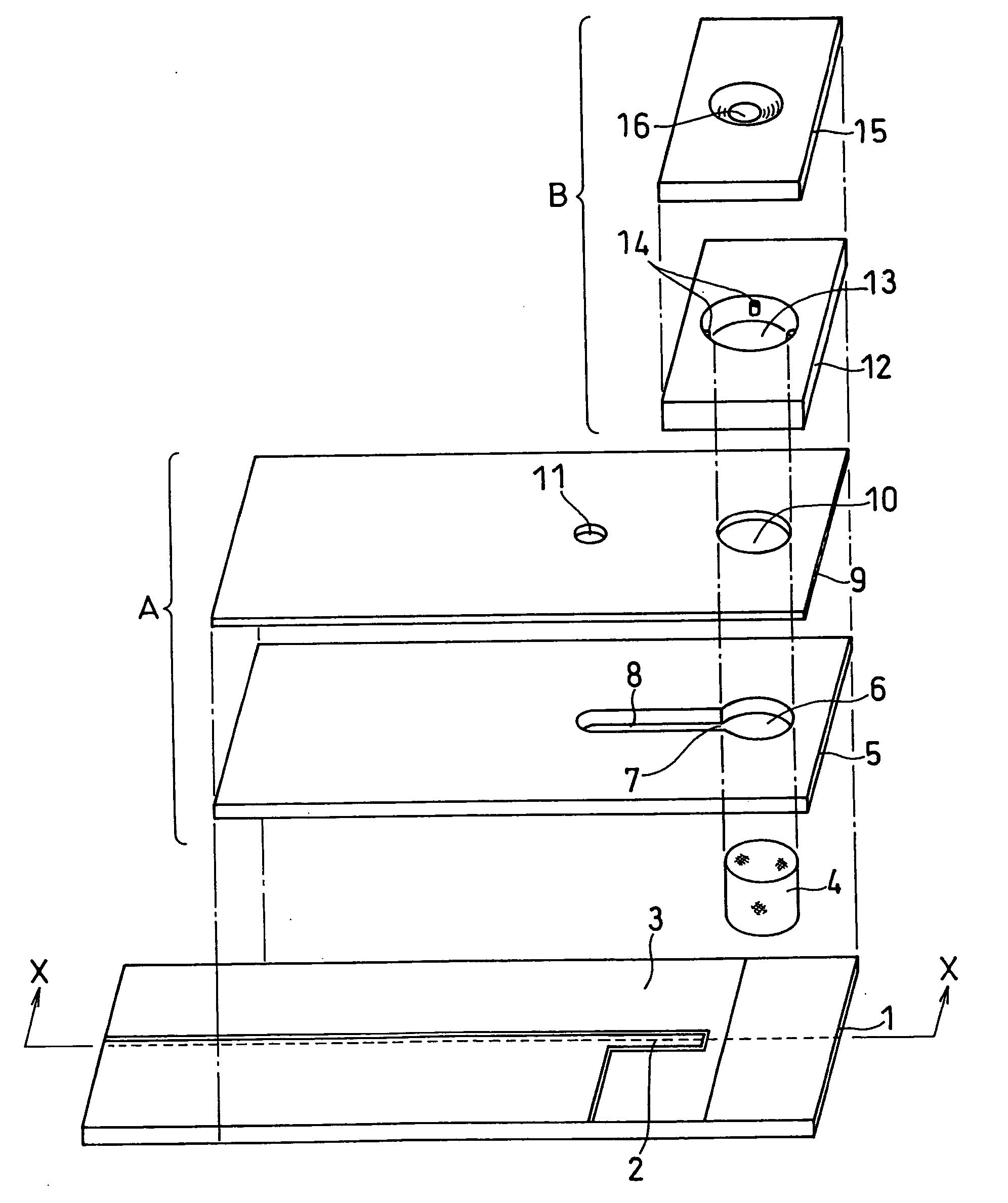
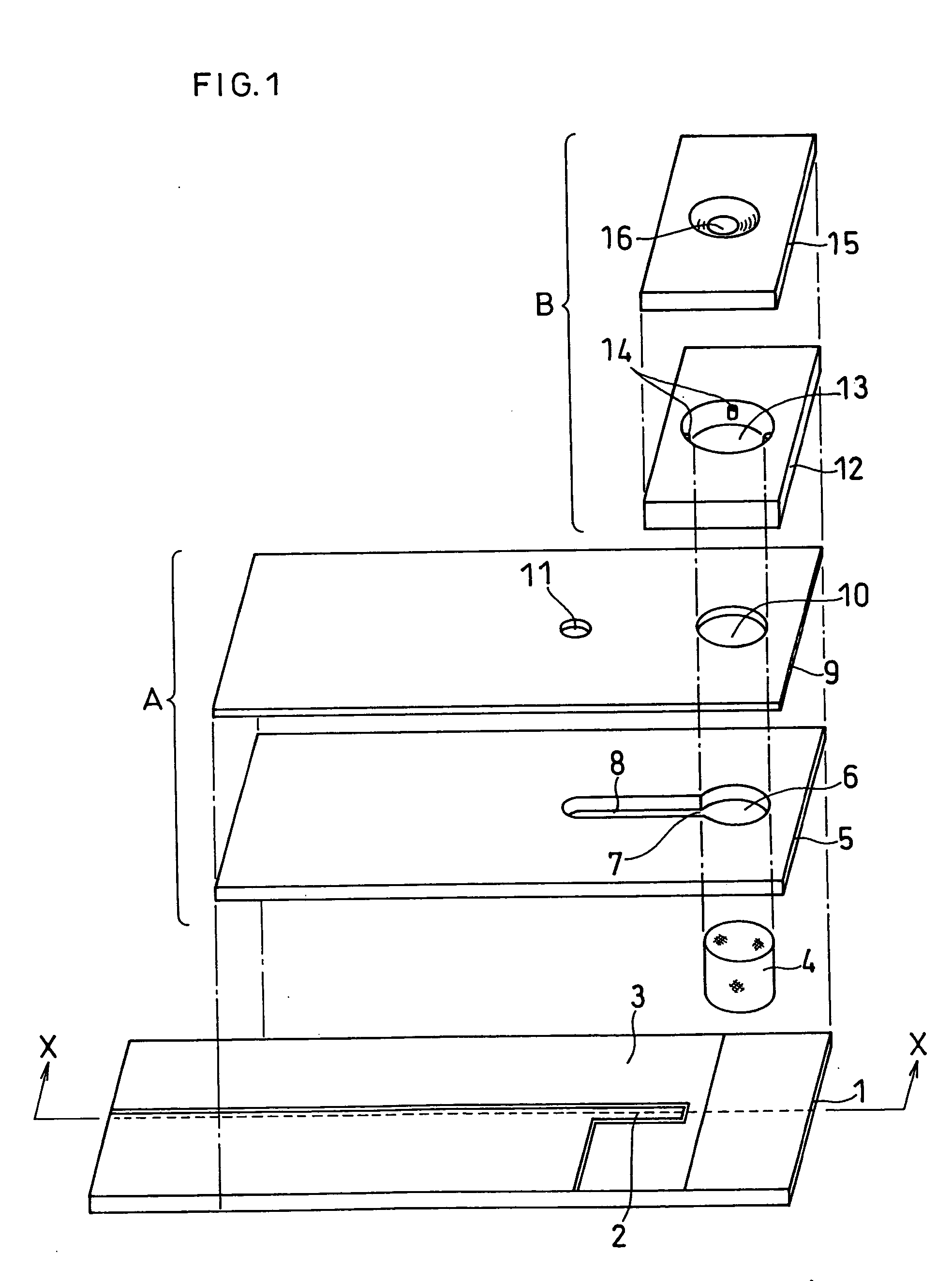
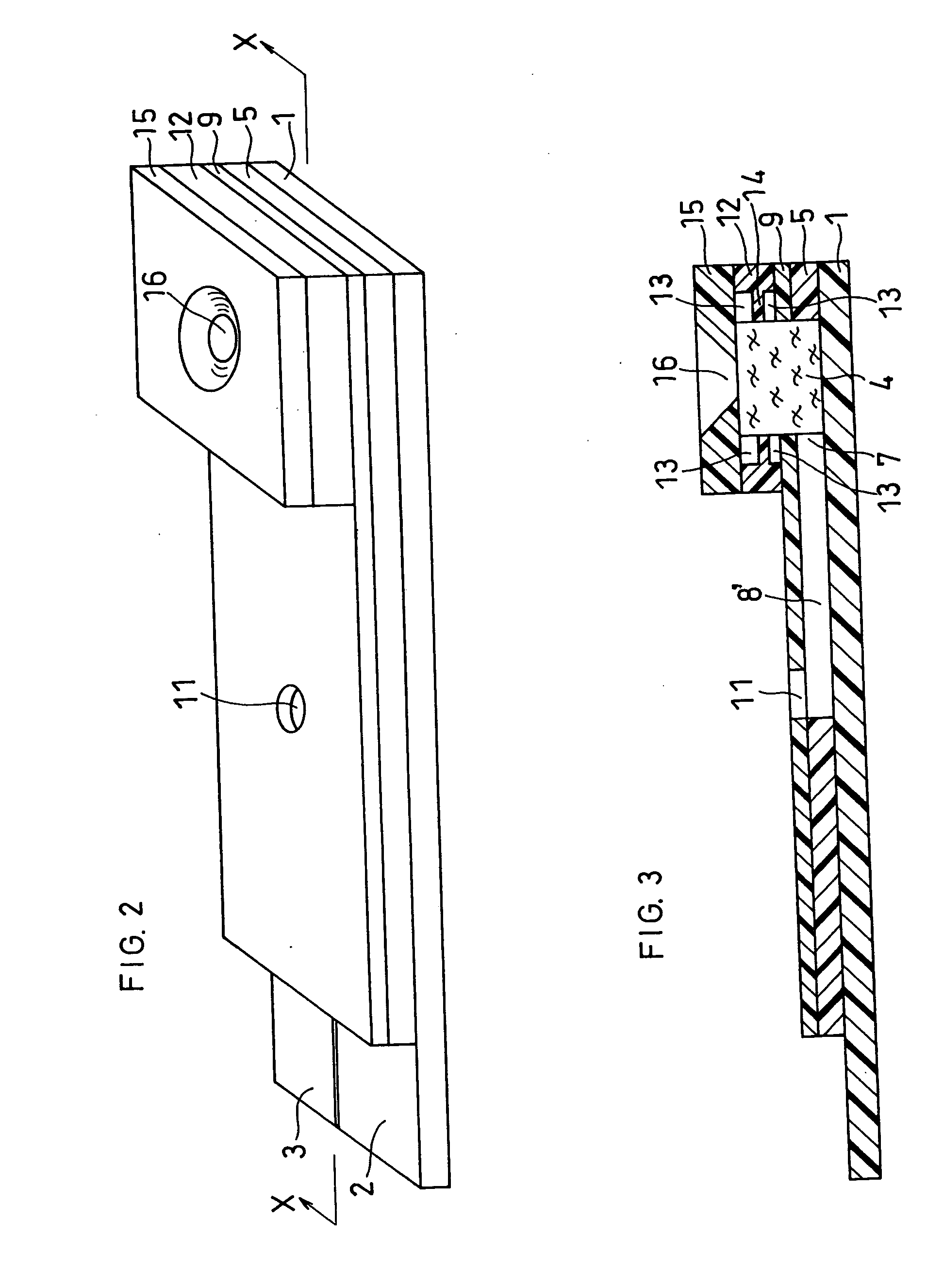
[0113]FIG. 5 is an exploded perspective view of a biosensor in accordance with Embodiment 2 obtained by further improving the biosensor in accordance with Embodiment 1 above. As shown in FIG. 5, the biosensor in accordance with the present invention has an insulating base plate 101 made of an insulating resin such as polyethylene terephthalate. In FIG. 5, on the left upper face of the base plate 101, a palladium portion is formed by means of sputtering, vapor deposition or the like, followed by laser trimming, to form an electrode system including a working electrode 102 and a counter electrode 103. The area of the electrode is determined corresponding to a width of a slit 108 formed on a spacer 105, as later described.

[0114] In the spacer 105 to be combined with the base plate 101 formed are the slit 108 for constituting the sample solution supply pathway, in the biosensor obtained after being assembled, an inlet 107 of the slit 108 and an aperture 106 which has a smaller diameter...

embodiment 3

[0135] A biosensor in accordance with Embodiment 3 of the present invention comprises: an insulating base plate; an electrode system having a measuring electrode and a counter electrode which are provided on the base plate; a reaction layer including at least oxidoreductase and an electron mediator; a sample solution supply pathway which includes the reaction layer in contact with the base plate and has an air aperture at the end; a sample solution dropping part for introducing a sample solution; and a first filter which is disposed between the sample solution supply pathway and the sample solution dropping part, without intruding into the sample solution supply pathway, and filters the sample solution in the vertical direction, where a filtrate is absorbed into the sample solution supply pathway due to capillary action and passes laterally from the inlet of the sample solution supply pathway toward the air aperture thereof, characterized in that the first filter is constituted by a...


PUM

PropertyMeasurementUnit
widthaaaaaaaaaa
widthaaaaaaaaaa
thicknessaaaaaaaaaa

Abstract

In order to provide a biosensor with high accuracy and excellent response where plasma obtained by filtration of blood rapidly arrives at an electrode system, in a biosensor comprising: an insulating base plate; an electrode system having a working electrode and a counter electrode which are provided on the base plate; a reaction layer including at least oxidoreductase and an electron mediator; a sample solution supply pathway which includes the electrode system and the reaction layer and has an inlet and an air aperture; a sample solution supply part for introducing a sample solution, which is in position apart from the sample solution supply pathway; and a first filter which is disposed between the sample solution supply pathway and the sample solution supply part for filtering the sample solution, where the filtrate filtered with the first filter is supplied into the sample solution supply pathway due to capillary action, the direction in which the sample solution passes through the first filter and the direction in which the filtrate passes through the sample solution supply pathway are made cross at right angles.

Description

TECHNICAL FIELD [0001] The present invention relates to a biosensor capable of carrying out rapid, highly-sensitive, simple determination of a specific component in a sample to be detected such as blood, serum and plasma, especially a biosensor capable of measuring glucose, total cholesterol and the like. BACKGROUDN ART [0002] A description is given to an example of a conventional biosensor in terms of a glucose sensor. As a typical example, there is a glucose sensor obtained by forming an electrode system including at least a measuring electrode and a counter electrode on an insulating base plate by a method such as screen printing and then forming an enzyme reaction layer including a hydrophilic polymer, oxidoreductase and an electron mediator on the electrode system. As oxidoreductase used is glucose oxidase; as the electron mediator used is a metal complex, an organic compound or the like, such as potassium ferricyanide, ferrocene derivative or quinone derivative. A buffer is ad...

Claims


Application Information

Patent Timeline
Patent Type & Authority Applications(United States)
IPC IPC(8): C12Q1/00C12Q1/60G01N27/403G01N33/487G01N33/49
CPCC12Q1/001G01N27/3272C12Q1/60C12Q1/006
Inventor HASEGAWA, MIWAYAMAMOTO, TOMOHIROWATANABE, MOTOKAZUNAKAMINAMI, TAKAHIROIKEDA, SHINYOSHIOKA, TOSHIHIKONANKAI, SHIRO
Owner PANASONIC CORP
Why Eureka
Try Eureka