Partial aortic occlusion devices and methods for cerebral perfusion augmentation

Inactive Publication Date: 2005-06-09
ZOLL CIRCULATION
View PDF66 Cites 55 Cited by
  • Summary
  • Abstract
  • Description
  • Claims
  • Application Information

AI Technical Summary

Benefits of technology

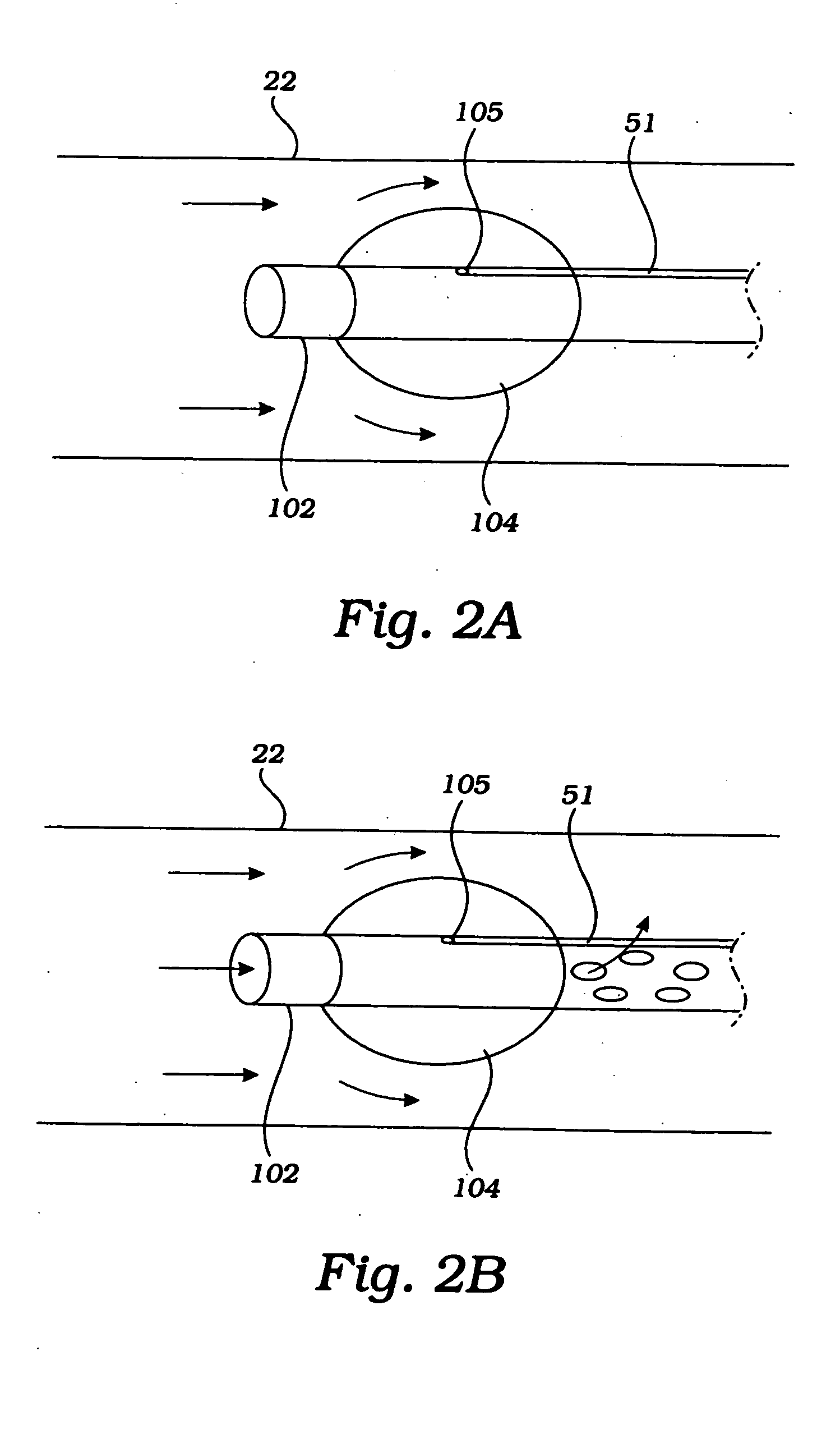
[0017] In still another embodiment, the constrictor comprises a first cylindrical balloon mounted to a distal end of the catheter, and a second toroidal balloon disposed about the cylindrical balloon. The chamber of the first balloon communicates with an inflation lumen. Blood flow occurs through the cylindrical balloon and through the center of the toroidal balloon. The toroidal balloon is expanded by inflation through a second and independent inflation lumen to reduce blood flow through the cylindrical balloon. In this manner, the first balloon provides an inflatable sleeve and the second toroidal balloon provides variable control of blood flow through the sleeve. Other embodiments include an expandable sleeve (not a balloon) surrounded by a toroidal balloon, or a spring mechanism, for adjustably constricting the flow of blood through the cylindrical sleeve.
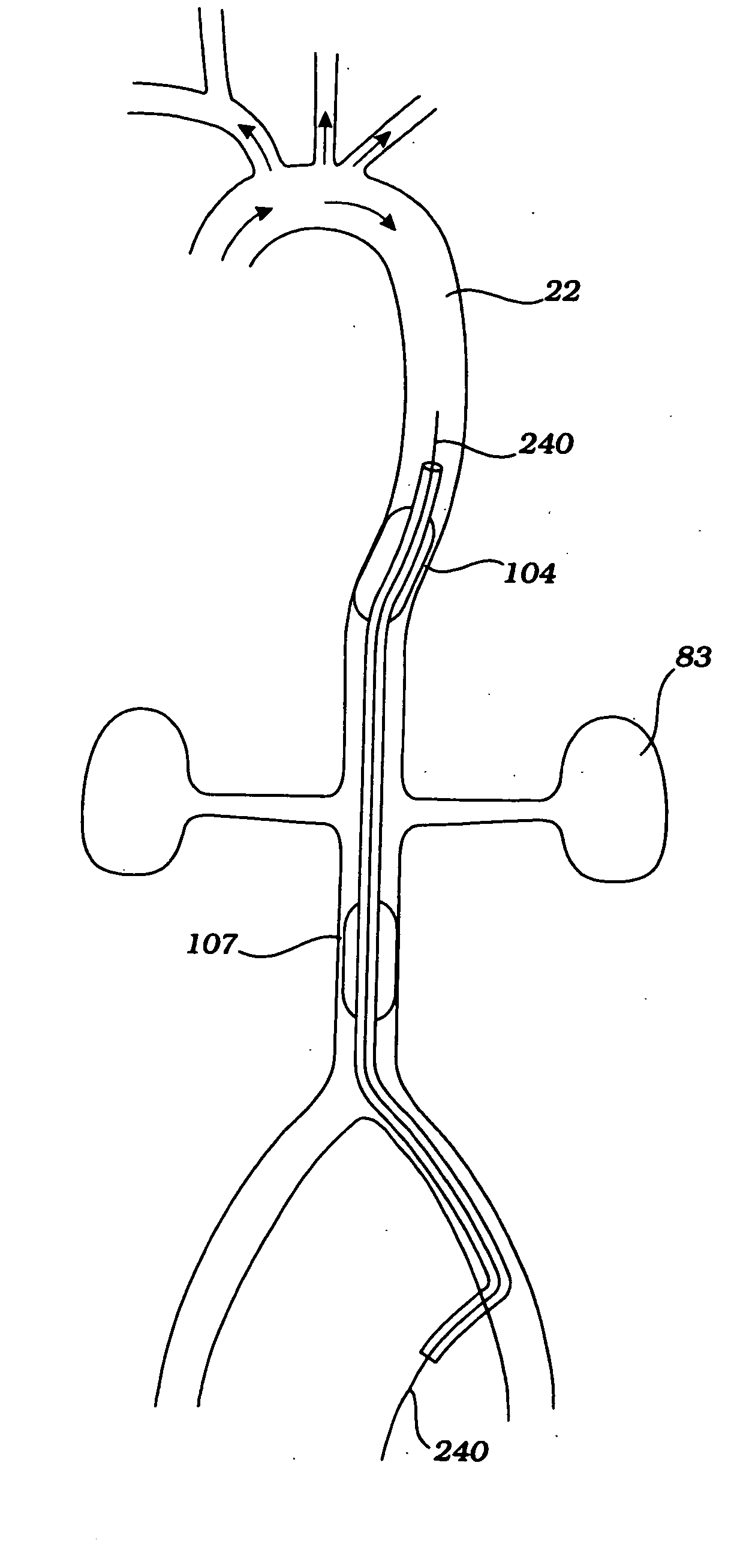
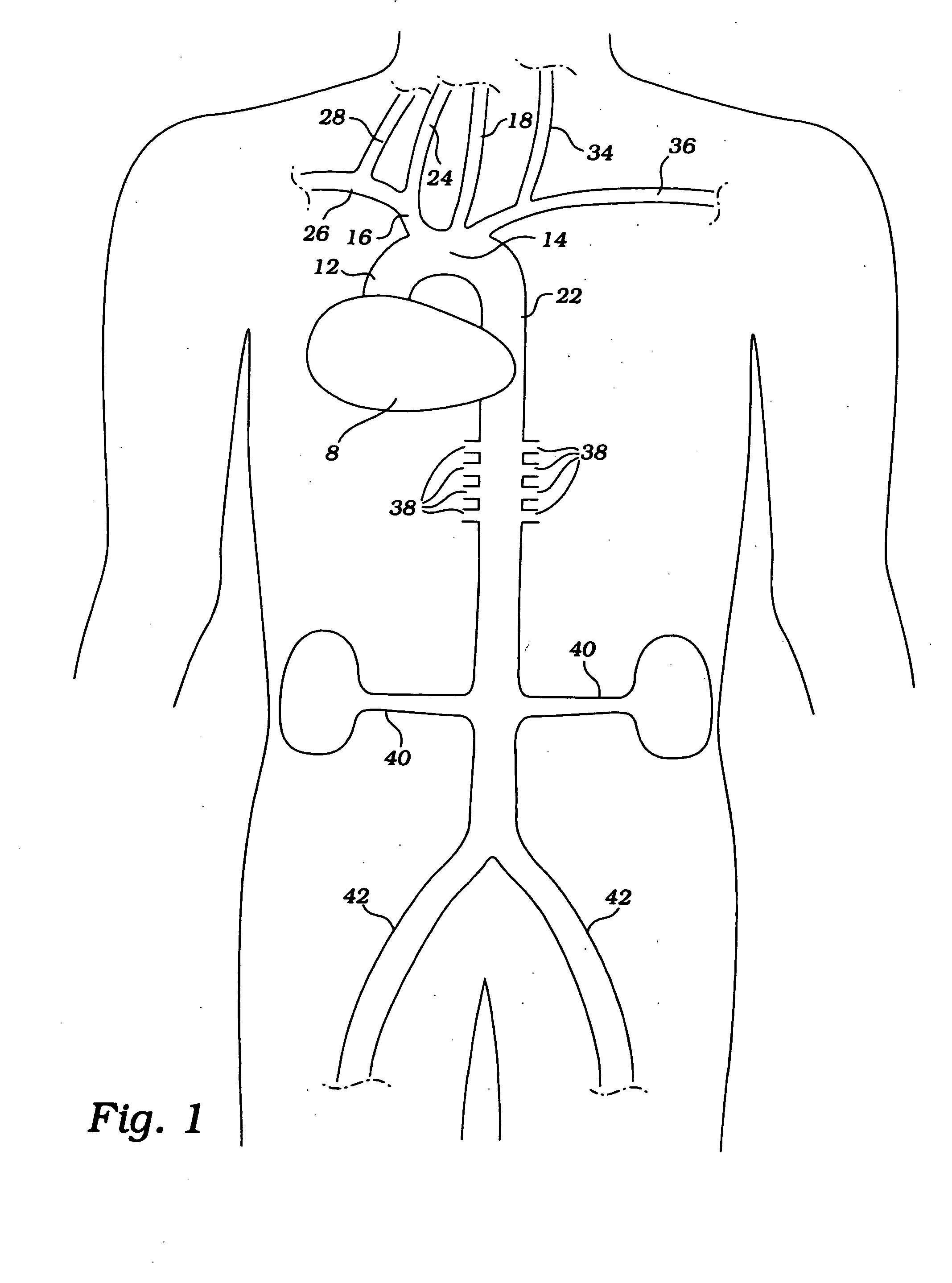
[0018] In use, the obstruction/occlusion/constriction devices described above are inserted into the descending aorta through an incision on a peripheral artery, such as the femoral, subclavian, axillary or radial artery, in a patient suffering from global or focal cerebral ischemia, typically stroke, shock or vasospasm, or during cardiac surgery (including any operation on the heart, with or without CPB), or during aortic surgery (during circulatory arrest, as for aortic arch surgery, repair of an abdominal aortic aneurysm, or thoracic aneurysm repair, to reduce perfusion and the amount of blood loss in the operating field). The devices can be introduced over a guide wire.
[0019] With assistance of transesophageal echocardiography (TEE), transthoracic echocardiography (TTE), intravascular ultrasound (IVUS), aortic arch cutaneous ultrasound, or angiogram, the constrictor is positioned downstream from the takeoff of the brachiocephalic artery and upstream from the renal arteries. When the constrictor is inserted in its preferred position, i.e., below the renal arteries, no visualization is necessary with any imaging equipment. The constrictor is expanded to at least partially obstruct blood flow in the aorta and maintained during systole, during diastole, or during systole and diastole. The constrictor preferably achieves continuous apposition to the wall of the vessel, resulting in reduced embolization. The pressure limiter, connected to the rotary unit and the pressure monitor, prevents the upstream and downstream blood pressure from exceeding, respectively, a set maximum and minimum pressure differential.
[0020] Flow rates can be varied within one cardiac cycle (e.g., 80% during systole, 20% during diastole, or 70% during systole, 30% during diastole), and every few cycles or seconds (e.g., 80% for 6 cycles, 20% for 2 cycles, or 70% for 5 cycles, 10% for 1 cycle). In certain cases it may be

Problems solved by technology

Patients experiencing cerebral ischemia often suffer from disabilities ranging from transient neurological deficit to irreversible damage (stroke) or death.
Shock is the state in which failure of the circulatory system to maintain adequate cellular perfusion results in reduction of oxygen and nutrients to tissues.
The most frequent cause of cardiogenic shock is myocardial infarction with loss of substantial muscle mass.
Pump failure can also result from acute myocarditis or from depression of myocardial contractility following cardiac arrest or prolonged cardiopulmonary bypass.
Mechanical abnormalities, such as severe valvular stenosis, massive aortic or mitral regurgitation, acutely acquired vent

Method used


Image

  • Partial aortic occlusion devices and methods for cerebral perfusion augmentation
  • Partial aortic occlusion devices and methods for cerebral perfusion augmentation
  • Partial aortic occlusion devices and methods for cerebral perfusion augmentation

Examples


example 1

[0194] In order to study the efficacy of the coarctation devices disclosed herein, an experiment was conducted using rats. The rat was placed under anesthesia, and an incision was made over one or more of the carotid arteries. The middle cerebral artery was ligated and the CCA was clamped using a hemostat to abolish blood flow to the ipsilateral cerebral hemisphere, thereby inducing a stroke. The aorta was then ligated, thereby causing immediate and sustained elevation in the systolic blood pressure (SBP), diastolic blood pressure (DBP), and mean arterial pressure (MAP) proximal to the constriction. It was found that the ligation tended to produce doubling of MAP.

[0195]FIG. 38 shows a plot of cerebral blood flow (cc blood / 100 grams brain tissue / min) versus time (minutes) in a rate stroke model. Cerebral blood flow (CBF) can be measured using Laser Doppler Flow (LDF) measurement. As shown in FIG. 38, IPSI refers to the cerebral hemisphere where the stroke was induced, CONTRA refers ...

example 2

[0204] Sections of rat brain were taken before and after deployment of the, devices disclosed herein using fluorescent-labeled capillary perfusion techniques. After induction of three-vessel stroke, the rat was injected with a red dye, followed by deployment of a coarctation device, followed by injection of a fluorescent green dye that has affinity for patent capillary. The rat is then sacrificed and sections of the rat brain were taken and exposed microscopically under fluorescent light. FIG. 39 depicts a normal rat brain having numerous fluorescent staining capillaries.

[0205] In stroke induced rat model using the method described in Example 1, 10 rats were used in a control group and 10 rats in a treatment group. In the control group (stroke but no coarctation) a fluorescent green dye was injected prior to sacrificing the animal as described above. A dramatic reduction in the number of patent capillaries is evident in the stroke center as depicted in FIG. 40 and in the stroke pen...

example 3

Infarct Volume Reduction Using Coarctation Device

[0206] Using the TTC technique (technetium stain) to determine infarct (stroke) volume, one hour of treatment with a coarctation device inflated at the level of the kidneys, and started 90 minutes after the onset of stroke (induced by CCA and MCA occlusion plus occlusion of contralateral carotid artery plus occlude CCA on good side for one hour), reduced stroke volume at 24 hours from 1100 to 400. Thus, one hour of treatment achieved a 66% reduction in stroke volume. In certain animals, up to 80% reduction in stroke volume was achieved, and the stroke was not visible at low magnification. Thus, the devices and methods disclosed herein provide for a reduction in stroke volume of at least 60%, more preferably at least 70%, more preferably at least 80%, and most preferably greater than 80%.


PUM


Abstract

Methods are provided for partial aortic obstruction for cerebral perfusion augmentation in patients suffering from global or focal cerebral ischemia. Alternatively, the methods can be used to partially obstruct aortic blood flow to condition the spinal cord to secrete neuroprotective agents prior to abdominal aortic aneurysm repair. Partial obstruction of a vessel can be accomplished by a device comprising an elongate catheter and a distally mounted expandable member. The expandable member may comprise one or two balloons. Other medical devices, such as an angioplasty, stent, or atherectomy catheter, can be inserted distal the expandable member to provide therapeutic intervention.

Description

[0001] This is a continuation of U.S. application Ser. No. 10 / 052,688, filed Jan. 18, 2002, which is a continuation of U.S. application Ser. No. 09 / 841,929, filed Apr. 24, 2001, now U.S. Pat. No. 6,743,196, all of which are incorporated herein by reference in their entirety.FIELD OF THE INVENTION [0002] The present invention relates generally to medical devices. More particularly, the invention relates to methods and devices for augmenting blood flow to a patient's vasculature. More particularly, the invention relates to apparatus and methods which provide partial obstruction (“coarctation”) to aortic blood flow to augment cerebral perfusion in patients with global or focal ischemia. The devices and methods also provide mechanisms for continuous constriction and variable blood flow through the aorta. BACKGROUND OF THE INVENTION [0003] Patients experiencing cerebral ischemia often suffer from disabilities ranging from transient neurological deficit to irreversible damage (stroke) or ...

Claims


Application Information

Patent Timeline
IPC IPC(8): A61B5/0215A61B17/00A61B17/12A61B17/22A61F2/06A61M25/00A61M25/06
CPCA61B5/0215A61M2230/30A61B17/12045A61B17/12109A61B17/12136A61B17/1219A61B2017/22054A61F2002/068A61M25/00A61M25/003A61M25/0032A61M25/0068A61M25/0069A61M25/0074A61M25/008A61M25/0082A61M25/0662A61M25/1011A61M2025/0002A61M2025/0034A61M2025/0073A61M2025/0081A61M2025/1052A61M2210/127A61B17/12036A61B5/4076A61B17/1204A61B6/481A61B17/12145A61F7/12A61F2007/126A61M25/0147A61M2230/005A61B2090/3966
Inventor BARBUT, DENISE R.KEITH, PETER T.BERHOW, STEVEN W.ST. GERMAIN, JON P.
Owner ZOLL CIRCULATION
Why Eureka
Try Eureka