Sensor devices containing co-polymer substrates for analysis of chemical and biological species in water and air

a technology of co-polymer substrates and sensors, applied in chemical methods analysis, material electrochemical variables, instruments, etc., can solve the problems of adversely affecting the analytical capacity of the sensor, affecting the substrate during sensor deposition, and common with the use of solvents

Inactive Publication Date: 2005-06-23
GENERAL ELECTRIC CO
View PDF12 Cites 60 Cited by
  • Summary
  • Abstract
  • Description
  • Claims
  • Application Information

AI Technical Summary

Benefits of technology

[0009] The present disclosure is directed to sensor devices comprising a substrate comprising a polycarbonate combined with at least one solvent resistance-imparting monomer and a sensor region comprising an analyte-responsive reagent having a predetermined response upon exposure to an analyte of interest. In some embodiments the sensor region covers a discrete area of the substrate.

Problems solved by technology

However, solvents commonly used for preparation of the sensor solution can negatively impact the substrate during sensor deposition.
These effects can include a change in surface morphology, crystallinity, transparency, geometrical size and shape, and other similar properties of the sensor which, in turn, can adversely affect the analytical capacity of the sensor.
In particular, two types of problems are common with the use of solvents.
First, a solvent of the sensor solution can attack the plastic substrate and distort one or more substrate properties which, in many cases, are critical for sensor functionality.
For example, if transparency is reduced because of solvent-induced haze, transmission optical measurement results will contain errors.
Similarly, if the substrate is to function as a waveguide, the distortion of geometrical shape by the solvent can lead to critical errors.
Thus, the wave-guiding capability will be reduced or lost.
The second problem which can arise with solvents is with respect to how the solvent interacts with the substrate.
The dissolved substrate material can negatively affect the sensor solution composition adding to the loss of desired signal after the sensor layer has formed.
However, this approach is complicated and reduces the reproducibility of measurements obtained.

Method used


Image

  • Sensor devices containing co-polymer substrates for analysis of chemical and biological species in water and air
  • Sensor devices containing co-polymer substrates for analysis of chemical and biological species in water and air
  • Sensor devices containing co-polymer substrates for analysis of chemical and biological species in water and air

Examples


example 1

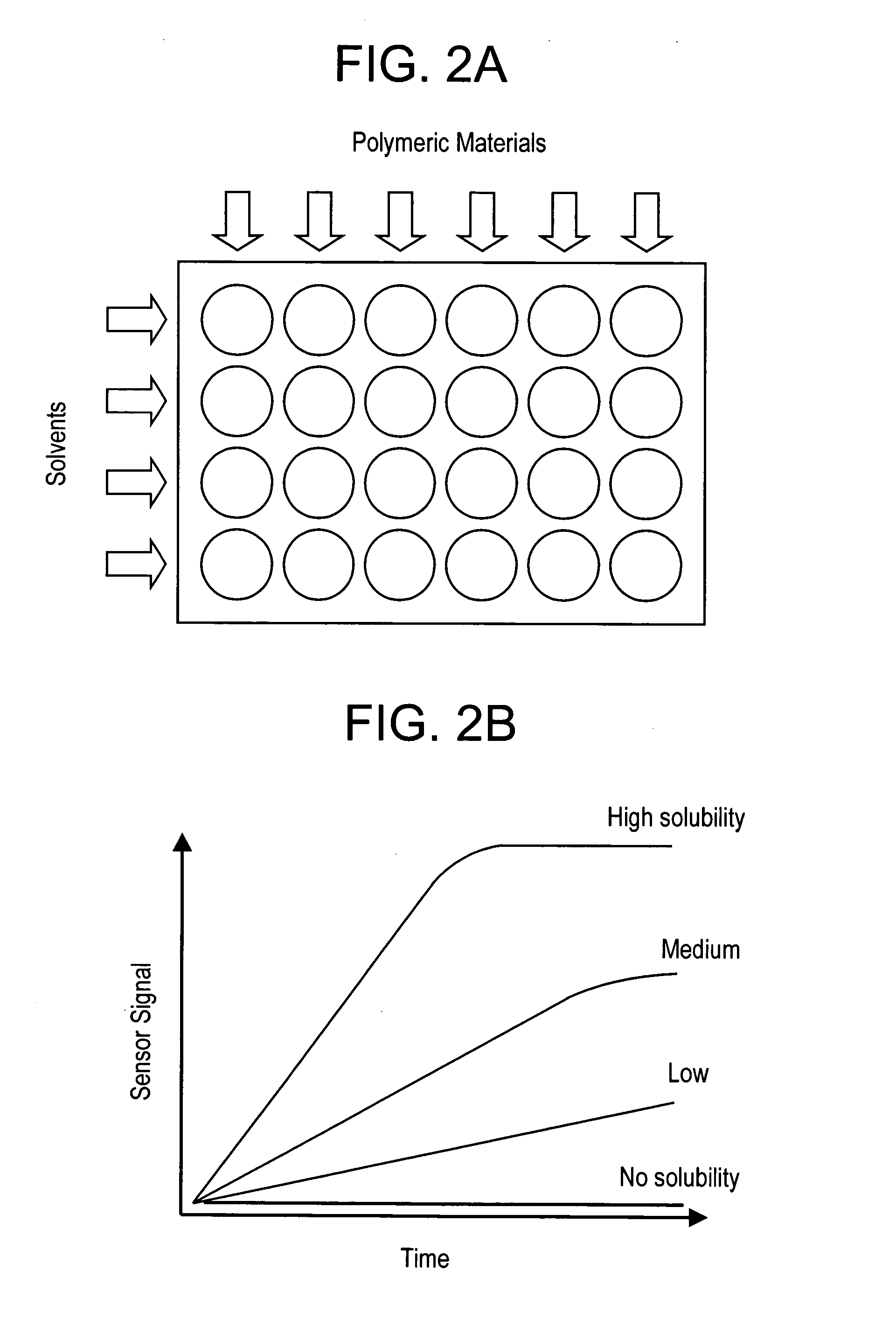
[0079] Polycarbonate copolymers were used as advanced polymeric substrates for sensor applications. Compositions of these copolymers included hydroquinone, methylhydroquinone, bisphenol-A, and biphenol. A 24-channel acoustic-wave sensor system, as disclosed in U.S. patent application Ser. No. 2002 / 0172620 was utilized for the evaluation of the solubility of these polymers by solvents of interest. The system permitted rapid determination of minute quantities of material deposited onto the surface of a thickness-shear mode (TSM) sensor from a solvent containing a polymer of interest. A crystal was exposed to a polymer / solvent combination and a residual dissolved material was quantified after sensor removal and solvent evaporation. As the mass increase of the crystal is proportional to the amount of dissolved material, mass increase mF may be detected as the change in the oscillation frequency ΔfF of the sensors utilizing the following equation:

ΔfF=−202(mF / A)(μQ ρQ)−1 / 2,

where f0 is ...

example 2

[0085] This example compared polycarbonate copolymers and BPA polycarbonate as sensor substrates. The effects of solvents used for preparation of sensor regions was compared for different sensor substrates. Sensor substrate materials and the ratio of their components (by mol %) are set forth below in Table 2. The solvents utilized were chloroform and THF.

TABLE 2Types of studied sensor substrates.Material #Description / mol % of componentsAOQ1020CBPC 104CPC134D30 / 20 / 50 HQ / RS / BPAE80 / 20 MeHQ / BPAFGlass slide

OQ1020C is an optical grade polycarbonate obtained from GE Plastics, Spain, with a Molecular Weight of about 18,000.

PC 104 and PC 134 are polycarbonates obtained from GE Plastics, The Netherlands, with Molecular Weights of about 30,000 and 35,000, respectively.

MeHQ = methylhydroquinone; BPA = bisphenol-A; HQ = hydroquinone

[0086] The comparison was done by the formation of two types of sensor regions. The first type was made by depositing a solution of nile red in chloroform (10 mi...

example 3

[0092] This experiment analyzed applications of polycarbonate copolymers as sensor substrates. Quantitative detection of chemical species using advanced polymeric substrates was achieved with an optical-based sensor system. The system, described above in Example 2, contained a portable white light source, a spectrometer, and a bifurcated fiber-optic bundle.

[0093] Detection of pH was performed by dissolving cellulose acetate and bromothymol blue in methyl ethyl ketone (MEK) and depositing the solution of this polymer and reagent onto a surface of an Izod bar made from material #2 (see Table 1 above). The film was produced by evaporation of the solvent at room temperature for several hours followed by baking at 80° C. for one hour. The Izod bar with a deposited sensor region was then immersed in a solution having varying levels of pH adjusted with NaOH or HCl with concentrations produced by adding known amounts of stock solutions of analyte. pH was adjusted by adding dropwise 100 mic...


PUM

PropertyMeasurementUnit
thicknessaaaaaaaaaa
thicknessaaaaaaaaaa
temperatureaaaaaaaaaa

Abstract

Sensor devices are disclosed possessing substrates having enhanced resistance to solvents. The sensor device (10) has a sensor region (12) deposited on a substrate (14). In optional embodiments, a protecting layer (16) is applied over the sensor region. The substrates include polycarbonates combined with solvent resistance-imparting monomers that result in a copolycarbonate substrate immune to attack by organic solvents commonly used in sensor deposition and improve the quality of the deposited sensor regions.

Description

BACKGROUND OF THE INVENTION [0001] This disclosure is directed to support materials, i.e., substrates, and methods for sensor deposition that provide sensors possessing improved optical quality and stability. These new properties are achieved utilizing different polycarbonate copolymers as sensor substrates. These polycarbonate copolymers are immune to attack by organic solvents commonly used in sensor deposition and improve the quality of the deposited sensor regions. [0002] In chemical sensor devices, an analyte-responsive reagent is typically incorporated into a support matrix such as a polymer, sol-gel, biomembrane, or similar material. See, e.g., Yang, et al., “Chemical Sensing Using Sol-gel Derived Planar Waveguides and Indicator Phases”, Anal. Chem. 1995, 67, 1307-1314; Potyrailo, et al., “Optical Waveguide Sensors in Analytical Chemistry: Today's Instrumentation, Applications and Future Development Trends”, Fresenius' J. Anal. Chem. 1998, 362, 349-373; Potyrailo, et al., “Ad...

Claims


Application Information

Patent Timeline
Patent Type & Authority Applications(United States)
IPC IPC(8): C08L69/00G01N21/09G01N21/76G01N21/80G01N29/02G01N29/036G01N29/22G01N31/00G01N33/00
CPCC08L69/00G01N21/09G01N21/766G01N21/80G01N29/022G01N29/036G01N29/222G01N2291/0423G01N33/00G01N2291/0256G01N2291/0422
Inventor POTYRAILO, RADISLAV ALEXANDROVICHMCCLOSKEY, PATRICK JOSEPHRAMESH, NARAYANSURMAN, CHERYL MARGARET
Owner GENERAL ELECTRIC CO
Why Eureka
Try Eureka