Compositions for preparing low dielectric materials containing solvents

Inactive Publication Date: 2005-09-08
VERSUM MATERIALS US LLC
View PDF21 Cites 42 Cited by
  • Summary
  • Abstract
  • Description
  • Claims
  • Application Information

AI Technical Summary

Benefits of technology

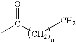
[0017] In one aspect, there is provided a composition for producing a silica-based material having a dielectric constant of about 3.7 or less comprising: an at least one silica source, a solvent, an at least one porogen, optionally a catalyst, and optionally a flow additive wherein the solvent boils at a temperature ranging from 90° C. to 170° C. and is selected from the group of compounds represented by the following formulas: HO—CHR8—CHR9—CH2—CHR10R11 where R8, R9, R10 and R11 can independently be an alkyl group ranging from 1 to 4 carbon atoms or a hydrogen atom; and R12—CO—R13 where R12 is a hydrocarbon group having from 3 to 6 carbon atoms; R13 is a hydrocarbon group having from 1 to 3 carbon atoms; and mixtures thereof.
[0018] In another aspect, there is provided a composition for forming a silica-based film having a

Problems solved by technology

Consequently, it may be impractical to use these low dielectric compositions due to the trade-off in dielectric constant with elastic modulus.
In some of these processes, temperature cycling of multiple layers may induce stresses due to the thermal coefficient of expansion mismatch between the different materials thereby causing cracking or delamination.
These impurities may result from residual levels of catalyst used in the manufacture of the chemical precursor reagents.
Such levels of residual catalytic impurities are often of little consequence in typical applications of these chemicals because the surfactant is often used at such low levels that the catalytic impurities imparted by the surfactant become insignificant in the final formulation.
A further source of impurities may result from an inattention to detail, such as packaging or handling outside a clean room, because such stringent purity requirements are not needed for typical applications.
U.S. Pat. No. 6

Method used


Image

  • Compositions for preparing low dielectric materials containing solvents
  • Compositions for preparing low dielectric materials containing solvents

Examples


example 1

[0085] 22.5 g tetraethylorthosilicate (TEOS) and 22.5 g of methyltriethoxysilane (MTES) were added to 100 g of 1-pentanol and mixed thoroughly. 9.67 g of purified Triton X-114 was added to the silicate solution and agitated to obtain a homogeneous solution. In a separate bottle, 1 g of 2.4 wt % tetramethylammonium hydroxide in water (TMAH) was added to 24 g of 0.1 M nitric acid (HNO3). The HNO3 solution was added directly to the silicate solution. The entire composition was agitated for ˜30 minutes.

[0086] After allowing the composition to sit at ambient conditions for 12 to 24 hrs., the composition was filtered through a 0.2 micron Teflon filter. Approximately 1.2 milliliters (mls) of composition was dispensed onto a 4″ Si wafer in an open bowl configuration while spinning at 500 rpm for 7 seconds. At the completion of the dispense step, the wafer was accelerated to 1800 rpm for 40 seconds to complete the evaporation process.

[0087] The wafer was then calcined in air at 90° C. for ...

example 2-13

[0088] The same procedure that was used in example 1 was repeated except that 100 g of the solvent or a 50 / 50 mole percent mixture of solvents with the appropriate combination of boiling point, surface tension, viscosity, and solubility parameter were used in place of the 1-pentanol. Examples 2-5 and 12-13 are comparative compositions that use one or more solvents that fall outside the preferred ranges of physical and chemical properties. The properties of films made from compositions 1 through 13 are provided in Table II.

TABLE IIDielectricDe-Example #SolventConstantHomogenousStriationswettingUniformity2dipropylenen / tyesyesyesno(Comparative)glycol3propylenen / tnoyesyesno(Comparative)glycol(emulsion)4diacetonen / tnoyesyesno(Comparative)alcohol(two-phase)5Cyclohexanonen / tyesyesnono(Comparative)(particles)12 Ethanol2.05yesyesnoyes(Comparative)13 ethyl acetate2.06yesyesnoyes(Comparative)6propylene2.06yesnonoyesglycol propylether72-methyl-1-2.07yesnonoyespentanol11-pentanol2.07yesnonoyes...

example 14

[0090] 97.3 g TEOS, 97.3 g MTES, 497.3 g of 1-pentanol, and 108.1 g of a catalyst solution (103.7 g of 0.1 M HNO3, and 4.3 g 2.4 wt % TMAH) were combined together and mixed until homogeneous. The solution was stirred at 60° C. for 2 hours. After 2 hours at 60° C., the solution was concentrated by removing ˜20 wt % of the volatile components from the mixture using a rotary evaporator at 60° C. (removed 160 g of ethanol, water, and pentanol). The solution was cooled back to room temperature. 160 g of 1-pentanol was added to the formulation and stirred until homogeneous. 69.9 g of Triton X-114 was then added to the solution and mixed to insure homogeneity of the composition.

[0091] After aging at room temperature for 16 to 24 hours, the composition was filtered through a 0.2 micron Teflon filter. 4 mls of the filtered composition was dispensed, in a process tool with an open spinning bowl configuration, onto a 8″ Si substrate spinning at 500 rpm (dispense time ˜8 seconds) before accele...


PUM

PropertyMeasurementUnit
Temperatureaaaaaaaaaa

Abstract

Silica-based materials and films having a dielectric constant of 3.7 or below and compositions and methods for making and using same are disclosed herein. In one aspect, there is provided a composition for preparing a silica-based material comprising an at least one silica source, a solvent, an at least one porogen, optionally a catalyst, and optionally a flow additive wherein the solvent boils at a temperature ranging from 90° C. to 170° C. and is selected from the group of compounds represented by the following formulas: HO—CHR8—CHR9—CH2—CHR10R11 where R8, R9, R10 and R11 can independently be an alkyl group ranging from 1 to 4 carbon atoms or a hydrogen atom; and R12—CO—R13 where R12 is a hydrocarbon group having from 3 to 6 carbon atoms; R13 is a hydrocarbon group having from 1 to 3 carbon atoms; and mixtures thereof.

Description

CROSS-REFERENCE TO RELATED APPLICATIONS [0001] This application claims the benefit of U.S. Provisional Application No. 60 / 549,251, filed 2 Mar. 2004.BACKGROUND [0002] The present invention relates generally to a material suitable for use, for example, in electronic devices. [0003] There is a continuing desire in the microelectronics industry to increase the circuit density in multilevel integrated circuit devices such as memory and logic chips in order to improve the operating speed and reduce power consumption. In order to continue to reduce the size of devices on integrated circuits, it has become necessary to use insulators having a low dielectric constant to reduce the resistance-capacitance (“RC”) time delay of the interconnect metallization and to prevent capacitive cross talk between the different levels of metallization. Such low dielectric materials are desirable for premetal dielectric layers and interlevel dielectric layers. [0004] Typical dielectric materials for devices...

Claims


Application Information

Patent Timeline
IPC IPC(8): C01B33/16C09D5/25C08L83/04C09D183/02C09D183/04C09D183/14C09D201/00H01L21/312H01L21/316H01L21/469H01L21/4763H01L21/768H01L23/522
CPCH01L21/02126H01L21/02203H01L21/02216H01L21/31695H01L21/02337H01L21/3122H01L21/02282B42D3/08B42D3/10B42B5/10B42F13/16B42P2241/02
Inventor WEIGEL, SCOTT JEFFREYKHOT, SHRIKANT NARENDRAMACDOUGALL, JAMES EDWARDBRAYMER, THOMAS ALBERTKIRNER, JOHN FRANCISPETERSON, BRIAN KEITH
Owner VERSUM MATERIALS US LLC
Why Eureka
Try Eureka