However there are many files for each of the diverse requirements of the
design flow and often a number of the files are proprietary to one vendor and unusable by another vendor's tool.
Imaging subwavelength features onto the substrate is a significant challenge even if various sophisticated resolution enhancement techniques are used.
The result is in poor light / dark
image contrast between the features desired to be printed and those that are not and
distortion in the printed features in comparison to the designer's ‘target
layout.’ Despite resolution enhancement efforts, distortions of the printed features may persist in comparison with the designer's desired target
layout.
The
physics and action of the photolithographically printed enhanced resolution circuit features can be quite complex to non-specialists and is typically highly non-intuitive, particularly to non-lithographers.
Furthermore, the proper application of RETs typically requires sophisticated optical models, large amounts of numerical
simulation, and specialized personnel.
PSM masks typically require definition of multiple materials and a more complex manufacturing sequence than conventional chrome-on-glass (COG)
mask technology.
Typically the
photomask data files can be huge, and the sheer volume of data and data transfer throughout the systems involved in
mask fabrication can
impact the available efficiencies of the mask fabrication cycle as the data are unordered and non-prioritized.
However determining a given defect's
potential impact and criticality is often ambiguous or very time intensive.
With the exception of gross defects, many defects are poorly correlated with a functional outcome.
Subwavelength
lithography further complicates correlating defects with functional results.
Since many features are inherently distorted, defect screening based upon traditional, rather simple, uniform ‘visual’ criteria is increasingly difficult.
Furthermore the size of a defect on a photomask is not necessarily an indicator of the relative
impact on the resulting
silicon pattern due to the highly non-linear nature of subwavelength
photolithography.
Compounding this difficulty is the fact that the defect will
impact various physical features of the same size and shape on the
wafer very differently depending upon device or process context.
For example, a given
distortion of a shape used as a switching
transistor gate may be unacceptable whereas the same
distortion and shape in the context of a long interconnect may be wholly insignificant.
However, defect review is often ineffective and overly burdensome as the circuit context of the features impacted is typically not known and the interpretation of the
resultant distortions on the final IC is often highly non-intuitive due to the increasingly complex non-linear
lithography and device (or other)
physics in-play.
Resolution enhancement technology (RET) features add to the difficulty as they are, at least in the case of OPC (optical proximity corrected), predistortions of the target
layout designed to achieve the proper
silicon pattern shape.
These RET features may themselves be distorted due to the various limitations of the mask writing process including grid snapping and temporal or thermal variations.
Under some circumstances of distortion, the RET feature may be worse than nothing at all.
Historically, the most sensitive features with the smallest margins have determined the margin for all features, although this is not efficient.
Due to fundamental inherent limitations in current and near-future optical lithography processes, the layout of the IC is no longer directly equivalent to the pattern printed on the eventual IC
wafer.
That is, they are so small in comparison with the lithography
system wavelength that they are not singularly resolvable by themselves.
Similarly, small sub resolution-size defects or positioning errors of circuit features may as well have disproportionately large impact; however the impact is destructive rather than beneficial.
Either size or positioning errors may result in very large errors on the
patterned substrate, necessitating that mask design and fabrication must be performed with sufficient precision.
As a result, the patterned feature fidelity and dimensional accuracy are far more difficult to attain as compared to previous generations.
This exposes a significant problem impacting the IC industry.
Furthermore, due to the necessity to mitigate increasingly severe optical proximity effect distortions through resolution enhancement techniques at the mask level, the overall polygonal figure count is skyrocketing at a superlinear rate.
As a result, this increased use of RETs dramatically complicates mask fabrication while increasing costs and other complexities.
As previously discussed, even a moderate mask error enhancement factor, or MEEF, may cause a small error in the mask to be magnified disproportionately and often non-intuitively.
Extreme accuracy may therefore be required.
However, not all features have high MEEF and not all features have extreme fidelity needs to achieve the IC's design functional specifications.
In fact many features are currently constructed and inspected to much higher accuracy specifications than are actually required, complicating mask fabrication and inspection unnecessarily.
These factors have led to increases in the time it takes to create masks, and in the number of errors impacting mask elements, and to the higher costs associated with
sub wavelength mask process.
Many are overused and unneeded corrections and are often applied due to a lack of sophistication of the design, analysis, and fabrication tools currently in use.
As a result, while RET is necessary, it can also be problematic needlessly increasing costs without desired functional improvements, and, when non-optimal, may even be responsible for decreasing yield.
Beneficial effects which may result from additional care such as from increasing the write time with reduced write energy may be offset by the negative effects resulting from thermal and chemical changes in the
photoresist caused by other writing events as well as errors due to mechanical or environmental instabilities which occur over longer times. As such, there may be a tradeoff between optimizing writing speed and accuracy.
However, the
design data and ‘
design intent’ information usually are not available since it resides in a different
database, from which only the geometry information was copied.
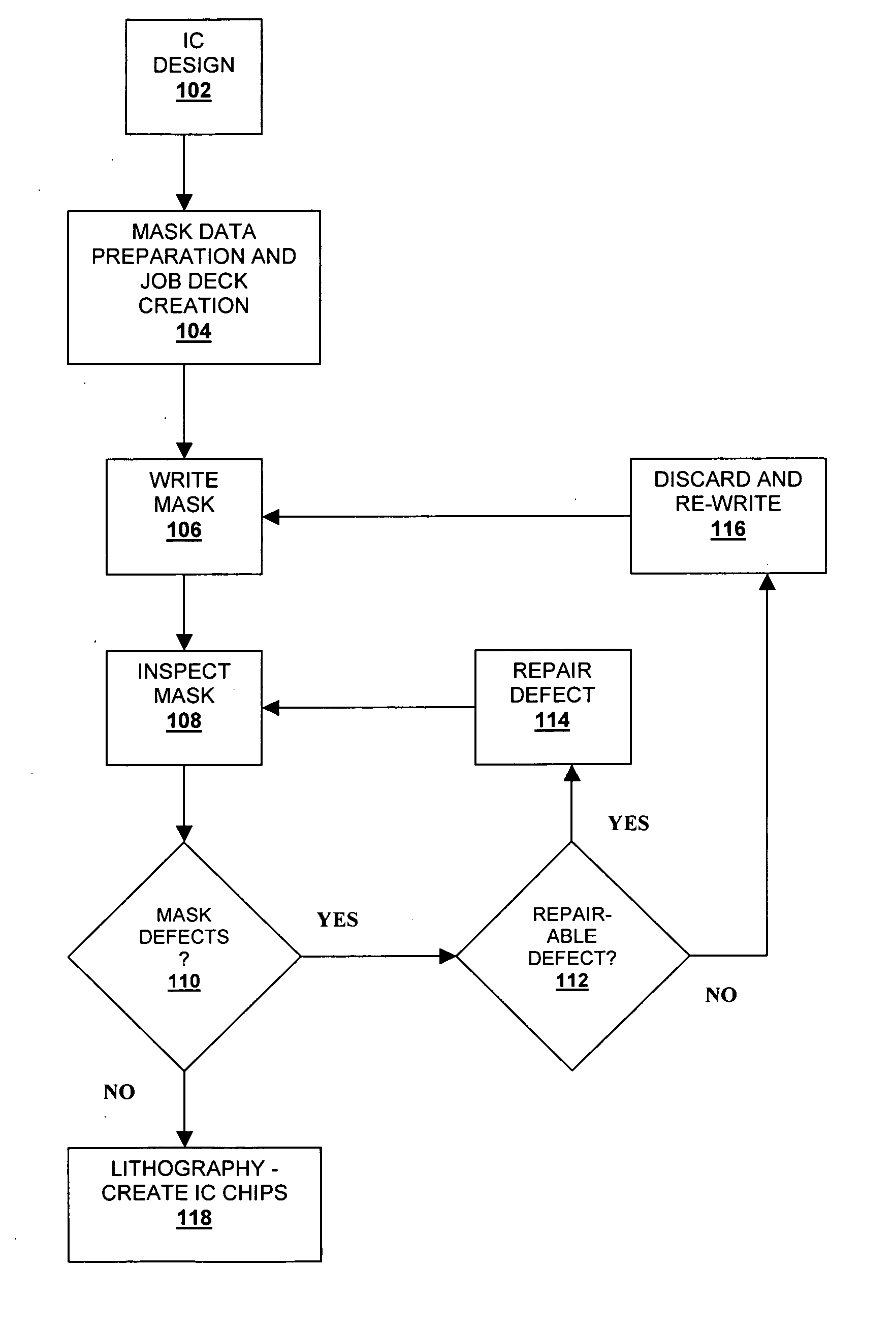
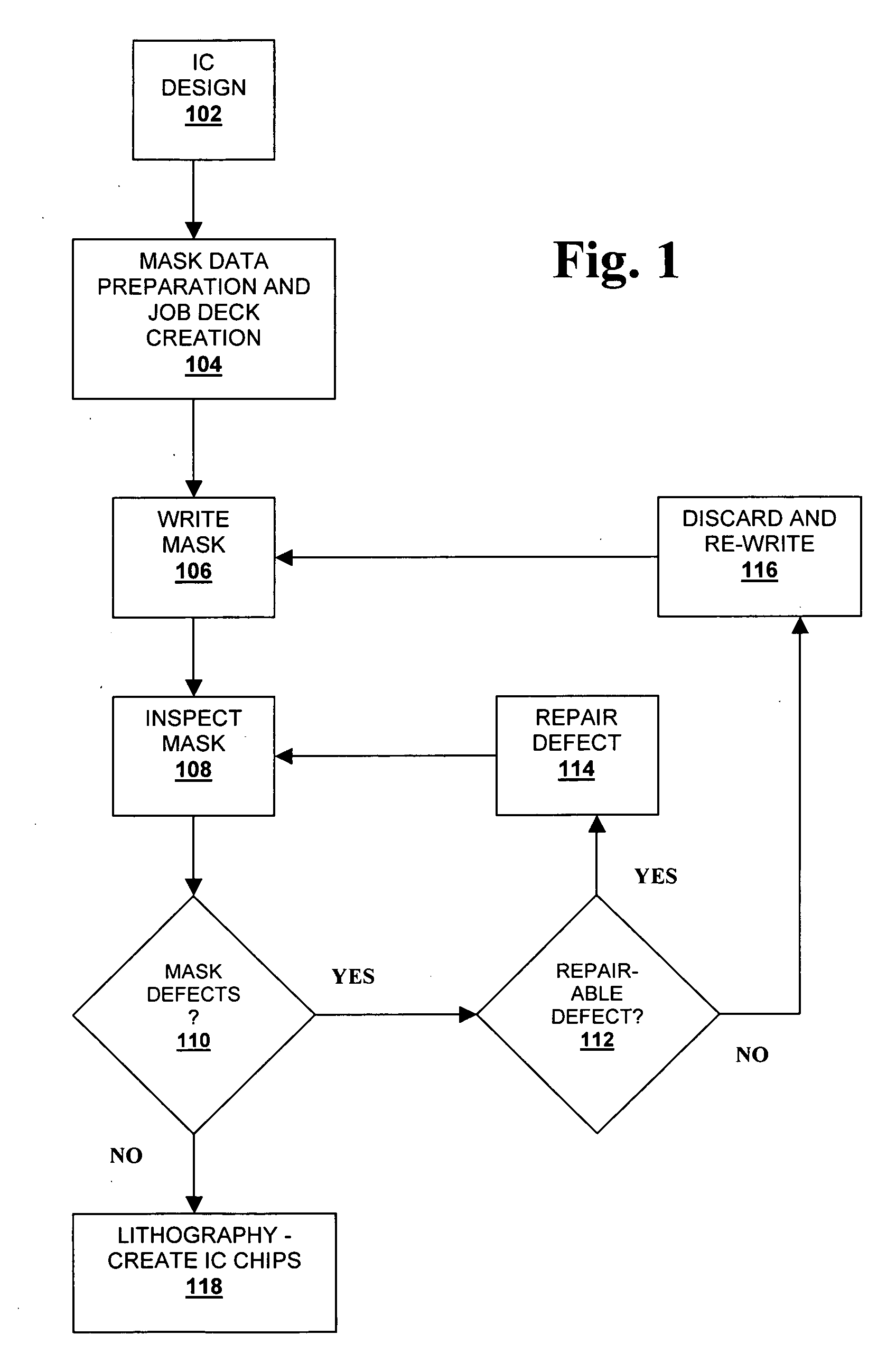
Typically, deviations from the ideal are considered defects.
An “unrepairable defect” might be a defect that cannot be cost-effectively fixed by
repair processes such as focused
ion-milling or equivalent deposition repair techniques, for example.
For example, a mask repair performed by
ion beam milling or other
processing may be more time-consuming and expensive than writing a new mask.
Additionally, mask correction often creates further defects in a mask, as it may add unwanted material during the
ion milling process or alternatively may erode the mask elements in some unwanted manner.
Merely handling the mask may alter or damage it through any number of means, including
electrostatic discharge (ESD).
Such a cycle is often costly and time-consuming.
Despite the amount of care and expense focused on the manufacture of the photomask inherent printing distortions are inevitable due to the nature of subwavelength, or low-k1 lithography.
Not all distorted features are damaging to the function of the circuit and application of extreme measures in writing and inspection may be largely ineffective,
time consuming and highly costly.

