[0015] Inventors of the present invention have investigated vigorously in order to solve the problems described above, and have found the following experiences or discoveries. Specifically, certain organometallic complex exhibiting phosphorescent
luminescence is suitable as a
luminescent material and color conversion material in an organic EL element and an organic EL element and an organic EL display using the organometallic complex, for example, as a luminescent material, color conversion material, etc. have excellent lifetime and light-emitting efficiency, thermal and
electrical stability, etc. and high performance.
[0019] In each of the organometallic complexes from the first organometallic complex to the third organometallic complex, the color of the emitted light can be modified by varying the skeletal structure or substituents of the one ligand, or the other ligand or dithiolate ligand. As the
metal center is rhenium (Re), which is a heavy
metal with very high
melting point and
boiling point, or the Group 8
metal element, the whole organometallic complex has excellent thermal and
electrical stability. Moreover, in the third organometallic complex when the dithiolate ligand is a aliphatic dithiolate ligand or a heteroaromatic dithiolate ligand, the complex has more excellent stability to light and light-emitting
quantum efficiency, stronger
color intensity and satisfactory shelf stability compared with the case of an aromatic dithiolate ligand, if this complex is used for an organic EL element, high light-emitting efficiency, long lifetime and
high color conversion efficiency can be achieved.
[0020] Moreover, the one ligand is a bidentate ligand. In the first organometallic complex, a
nitrogen atom and
oxygen atom in the bidentate ligand are directly bonded to the rhenium (Re) atom, in the second organometallic complex, a
nitrogen atom and
carbon atom in the bidentate ligand are directly bonded to the rhenium (Re) atom, and in the third organometallic complex, two ligand atoms in the bidentate ligand are directly bonded to the Group 8 metal atom. In each case, the one ligand (the bidentate ligand) exhibits
strong interaction between the rhenium (Re) atom or the Group 8 metal atom. Thus, in an organic EL element or the like where each of the organometallic complexes from the first organometallic complex to the third organometallic complex is used as luminescent material, color conversion material, etc., when
electric field is applied to the organic EL element,
strong interaction between the one ligand and the rhenium (Re) atom or Group 8 metal atom effectively prevents singlet and triplet excitons that are generated in the organic rhenium complex from deactivating as
thermal energy,
rotational energy or the like without
radiation, and the energy is efficiently changed into
light energy as
fluorescence and
phosphorescence. Hence, if the organometallic complex is, for example, used as a luminescent material, color conversion material, etc. in an organic EL element, emission having excellent lifetime, high light-emitting efficiency, color conversion efficiency, etc. is obtained.
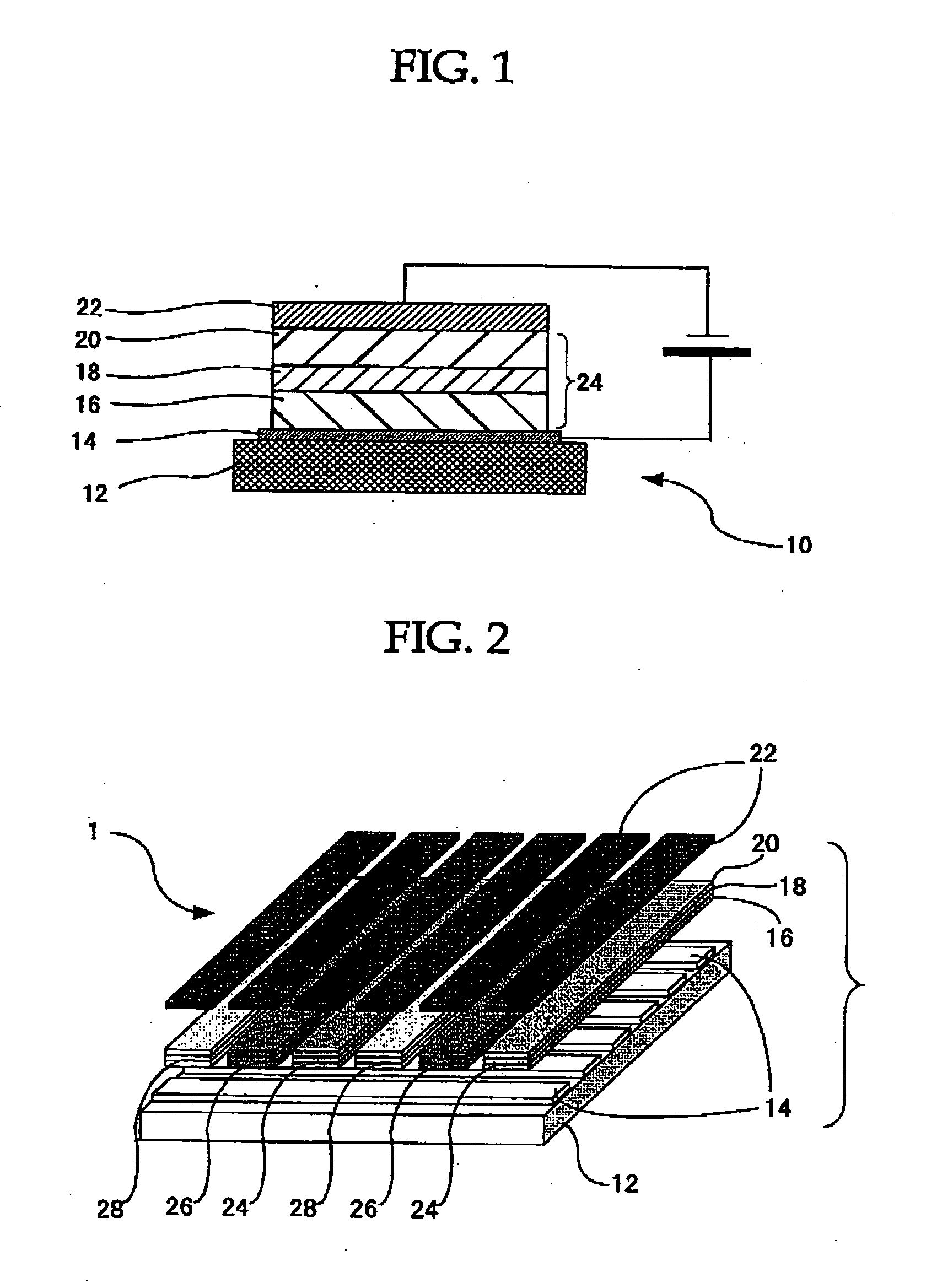
[0021] A first organic EL element of the present invention includes an organic thin film layer disposed between a positive electrode and a negative electrode. In the organic EL element, the organic thin film layer includes any one of the organometallic complexes from the first organometallic complex to the third organometallic complex at least as a luminescent material. As the first organic EL element contains the organometallic complex of the present invention, it is excellent in lifetime and light-emitting efficiency, durability, etc.
[0022] A second organic EL element of the present invention includes a color conversion layer, wherein the color conversion layer includes any one of the organometallic complexes from the first organometallic complex to the third organometallic complex as a color conversion material. In the second organic EL element, as the color conversion layer includes the organometallic complex of the present invention as a color conversion material, the second organic EL element is excellent in lifetime and color conversion efficiency, and by using only the organometallic complex without using host material together, for example,
ultraviolet light or
blue light can be directly converted into
red light.
[0024] The organic EL display of the present invention uses at least one of the organic EL elements from the first organic EL element to the second organic EL of the present invention. As the organic EL display uses the organic EL element of the present invention, it is excellent in lifetime and light-emitting efficiency, color conversion efficiency, etc.

