Lining for carbothermic reduction furnace

a technology of carbothermic reduction furnace and lining, which is applied in the field of linings and liners, can solve the problems of reducing the yield of aluminum, reducing the efficiency of the process, and reducing the efficiency of the process, and achieves the effect of effective heat dissipation system

Inactive Publication Date: 2005-11-17
SGL CARBON SE
View PDF15 Cites 26 Cited by
  • Summary
  • Abstract
  • Description
  • Claims
  • Application Information

AI Technical Summary

Benefits of technology

[0012] It is accordingly an object of the invention to provide a liner for a carbothermic reduction furnace which overcomes the above-mentioned disadvantages of the heretofore-known devices and methods of this general type. Specifically, the object is to provide inner linings to the steel shell of carbothermic reduction furnaces for the production of alumina, in particular linings made of refractory material and graphite, which provide protection against the molten slag, which do not contaminate the melt, which are not attacked by the CO-rich melt furnace atmosphere, and which provide an effective heat dissipation system in case of a power shut-off.

Problems solved by technology

In comparison with processes used to produce competing materials, such as steel and plastics, the process is energy-intensive and costly.
Unless recovered, these volatile species represent a loss in the yield of aluminum.
Besides the complexities is that operations safety system, the frozen slag layer is only formed after some initial start-up procedures during which the steel shell would be heavily attacked by the molten slag.
In addition, the melt furnace atmosphere is under pressure and contains substantial amounts of CO gas which easily diffuses through the frozen slag and then attacks the steel surface.
Furthermore, it is very difficult to maintain a uniform layer of the frozen slag under real operational conditions.
Hence, the above-described safety system would regularly cause power shut-offs making it difficult to run an efficient and continuous production process.
Finally, once the extremely hot molten slag reaches the steel shell it is a difficult task to cool the system down by the mere use of water spraying devices.

Method used


Image

  • Lining for carbothermic reduction furnace
  • Lining for carbothermic reduction furnace
  • Lining for carbothermic reduction furnace

Examples


example 1

[0052] 82 parts calcined low-iron coke and 18 parts of pitch having a softening point of 110° C. (Mettler) are mixed at 150° C., in an intense mixer with high energy input for 15 min. The mixture was extruded at 115° C. The extruded block was calcined for 3 to 4 weeks in a Riedhammer-type ring furnace with a final firing temperature of 900° C.

[0053] The thus obtained blocks were impregnated with impregnation pitch in autoclaves at 250° C. and pressures up to 25 bar. Afterwards they were rebaked within 1-3 weeks in rebaking furnaces at 1000° C. followed by graphitization in Castner type furnaces in firing rates up to 20 h at final temperatures surpassing 2800° C. The thus obtained graphite blocks were finally machined to the required dimensions.

example 2

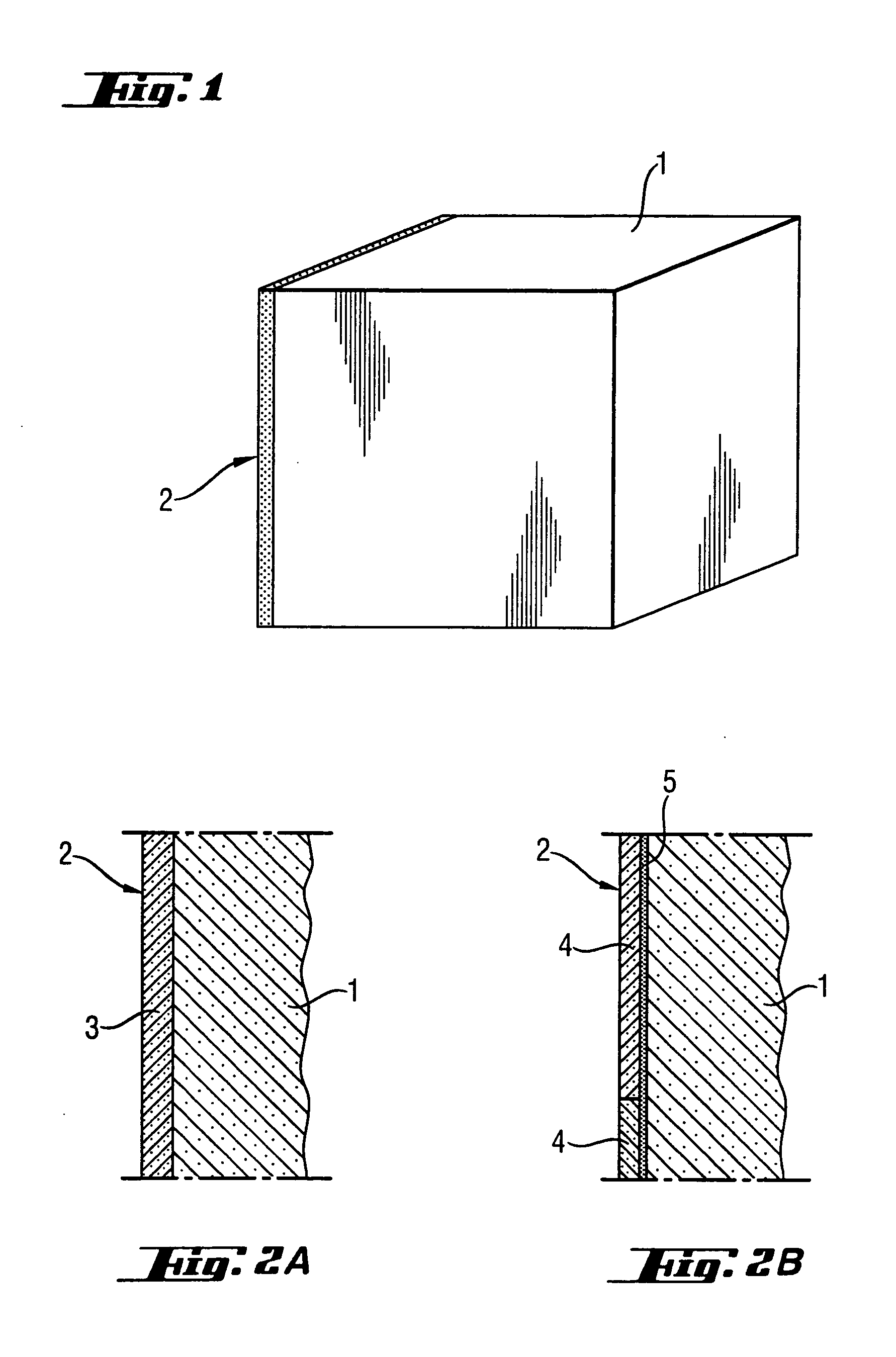
[0055] A graphite block obtained according to example 1 was machined to blocks of 1 m×1 m (height×width) and 1.2 m depth. One of the 1 m×1 m surfaces was coated with a slurry of 75% finely ground corundum and 25% Sialon particles which was heat treated to final temperatures above 2500° C. The thus obtained coating had a thickness of 3 mm.

[0056] The coated graphite lining was joined by high-temperature glue with other graphite linings manufactured in the same manner to a solid lining wall inside a carbothermic reduction furnace steel shell.


PUM

PropertyMeasurementUnit
thermal conductivityaaaaaaaaaa

Abstract

An inner lining for the steel shell of a carbothermic reduction furnace for the production of alumina has a base layer of graphite and a coating layer of refractory material. The refractory material is corundum (Al2O3) bound by Sialon (Si.Al.O.N). The lining structure provides protection against the molten slag and it is not attacked by the CO-rich melt furnace atmosphere. Further, the lining does not contaminate the melt and it provides an effective heat dissipation system in case of a power shut-off.

Description

CROSS-REFERENCE TO RELATED APPLICATION [0001] This application claims the benefit under 35 U.S.C. § 119 (e), of copending U.S. Provisional Application No. 60 / 571,604, filed May 13, 2004.BACKGROUND OF THE INVENTION [0002] 1. Field of the Invention [0003] The present invention relates to linings and liners made of graphite and other refractory materials for the production of aluminum by carbothermic reduction of alumina. [0004] 2. Description of the Related Art [0005] For a century the aluminum industry has relied on the Hall-Heroult process for aluminum smelting. In comparison with processes used to produce competing materials, such as steel and plastics, the process is energy-intensive and costly. Hence, alternative aluminum production processes have been sought. [0006] One such alternative is the process referred to as direct carbothermic reduction of alumina. As described in U.S. Pat. No. 2,974,032 (Grunert et al.) the process, which can be summarized with the overall reaction Al2...

Claims


Application Information

Patent Timeline
Patent Type & Authority Applications(United States)
IPC IPC(8): C04B35/103C04B35/52C04B35/532C04B35/63C04B35/66C22B21/02F27B17/00F27D1/00F27D1/16H05H1/00
CPCC04B35/103F27D1/0006C04B35/532C04B35/62635C04B35/6303C04B35/6316C04B35/64C04B35/66C04B2235/3217C04B2235/3869C04B2235/3873C04B2235/402C04B2235/422C04B2235/48C04B2235/6021C04B2235/661C04B2235/72C04B2235/77C04B2235/80C04B2235/9607C04B2235/9676C22B21/02F27B17/00C04B35/522
Inventor DAIMER, JOHANN
Owner SGL CARBON SE
Why Eureka
Try Eureka