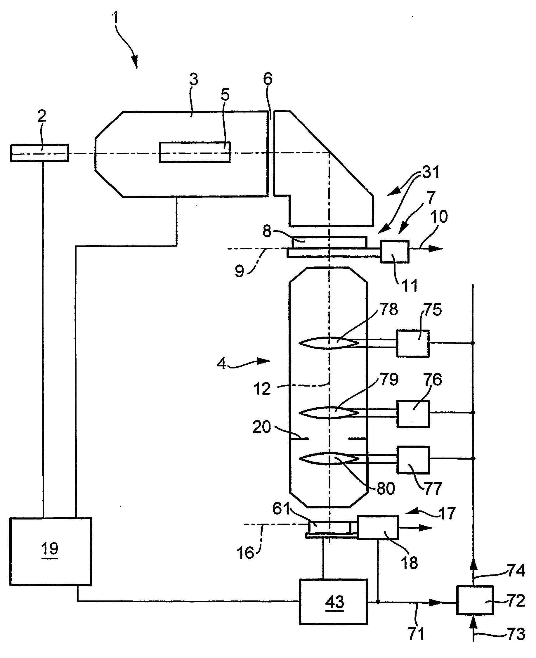
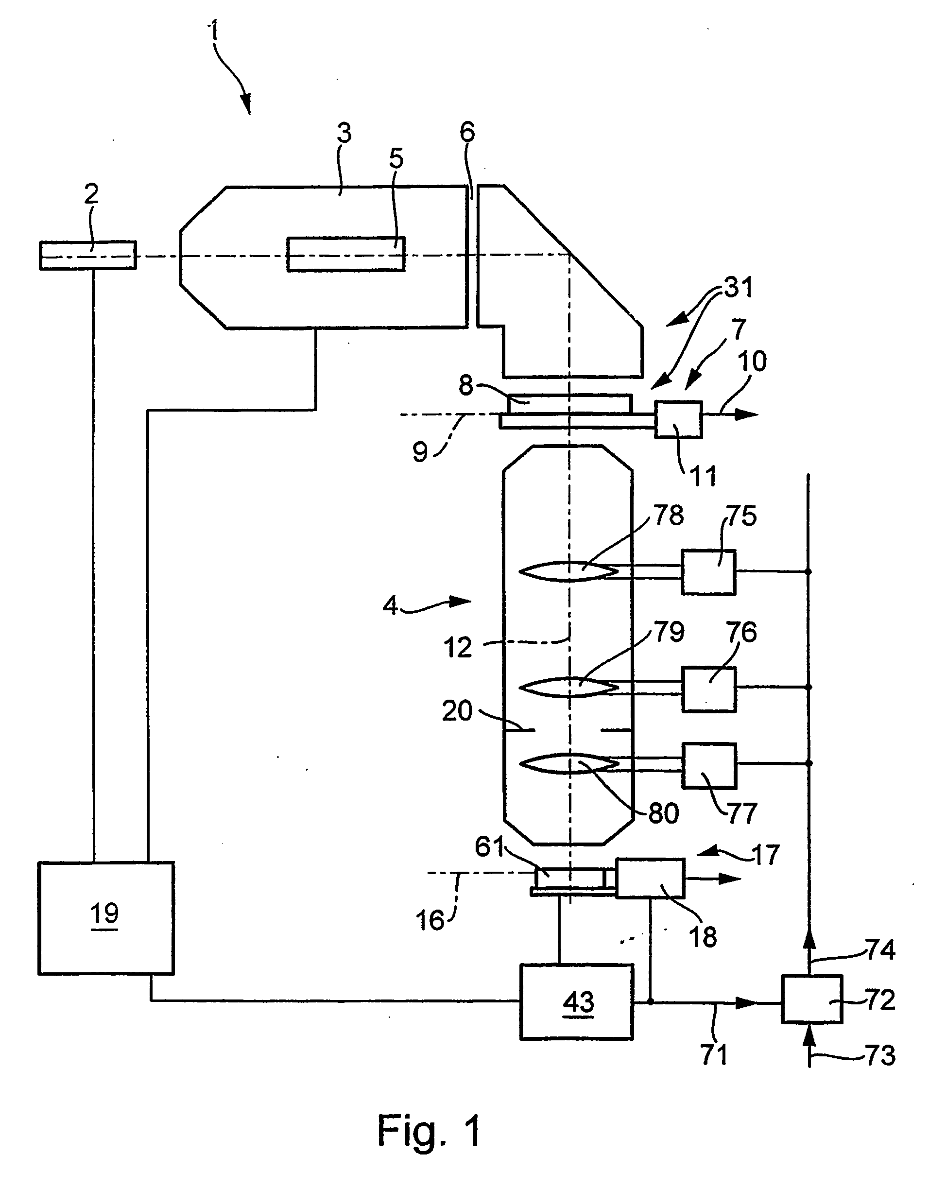
[0008] It is an object of the invention to provide an interferometric measuring device of the type mentioned at the beginning which is distinguished by a simple structure in the region of the wavefront source. It is another object to provide a measuring device which is capable of being integrated into a microlithographic projection
exposure installation in a simple manner and which permits rapid and fault-free measurements on projection objectives in their operating state.
[0014] It is thus possible to integrate the measuring structures for the interferometer, which were conventionally present in a separate measuring
reticle, in the usual reticles for the
chip structures. This therefore dispenses with the need, before an interferometric measurement of a projection objective, to replace the
chip production
reticle used during the
chip production by a separate measuring
reticle (for example a wavefront module). Instead, the measuring pattern which, because of its coherence-shaping properties, can also be designated a “coherence pattern”, is provided as part of the reticle used for the production of structured components, on this reticle. As a result, the costs for the provision of an interferometric measuring device can be reduced considerably. In addition, interferometric measurements on incorporated objectives are faster than was previously possible, which reduces the
machine downtimes and as a result increases the productivity of the projection
exposure installation. Moreover, it is possible in a particularly simple manner to obtain measuring data relating to projection objectives in good time in relation to the production process, in order for example to be able to counteract worsening of the
imaging quality in good time by means of suitable manipulations of the projection objective. Using measuring devices according to the invention, it is merely necessary, for the measurement, to replace the component arranged in the region of the
image plane of the projection objective and to be exposed, for example a
semiconductor wafer, for a short time by a
diffraction grating matched to the measuring structure. The spatially resolving
detector can be integrated permanently in the projection exposure installation or be capable of being replaced or interchanged together with the
diffraction grating.
[0018] The
diffraction grating, which can likewise be one-dimensionally or two-dimensionally periodic, is preferably formed as a function of the structure of the measuring pattern in such a way that only specific diffraction orders contribute to the interference at the
diffraction grating, for example only the zeroth and first diffraction orders. All of the diffraction grating types mentioned in DE 101 09 929, such as phase gratings, amplitude gratings or reflective gratings, are possible.
Diffraction gratings which in each case have a diffractive, periodic structure for different directions are preferred, which makes it possible to determine phase gradients in more than one direction from individual interferograms.
Diffraction gratings with periodicity directions running orthogonally to one another, for example chessboard gratings or crossed gratings, are favourable, but also possible are gratings with other symmetries, for example with angles of 45°, 60° or 120° between periodicity directions.
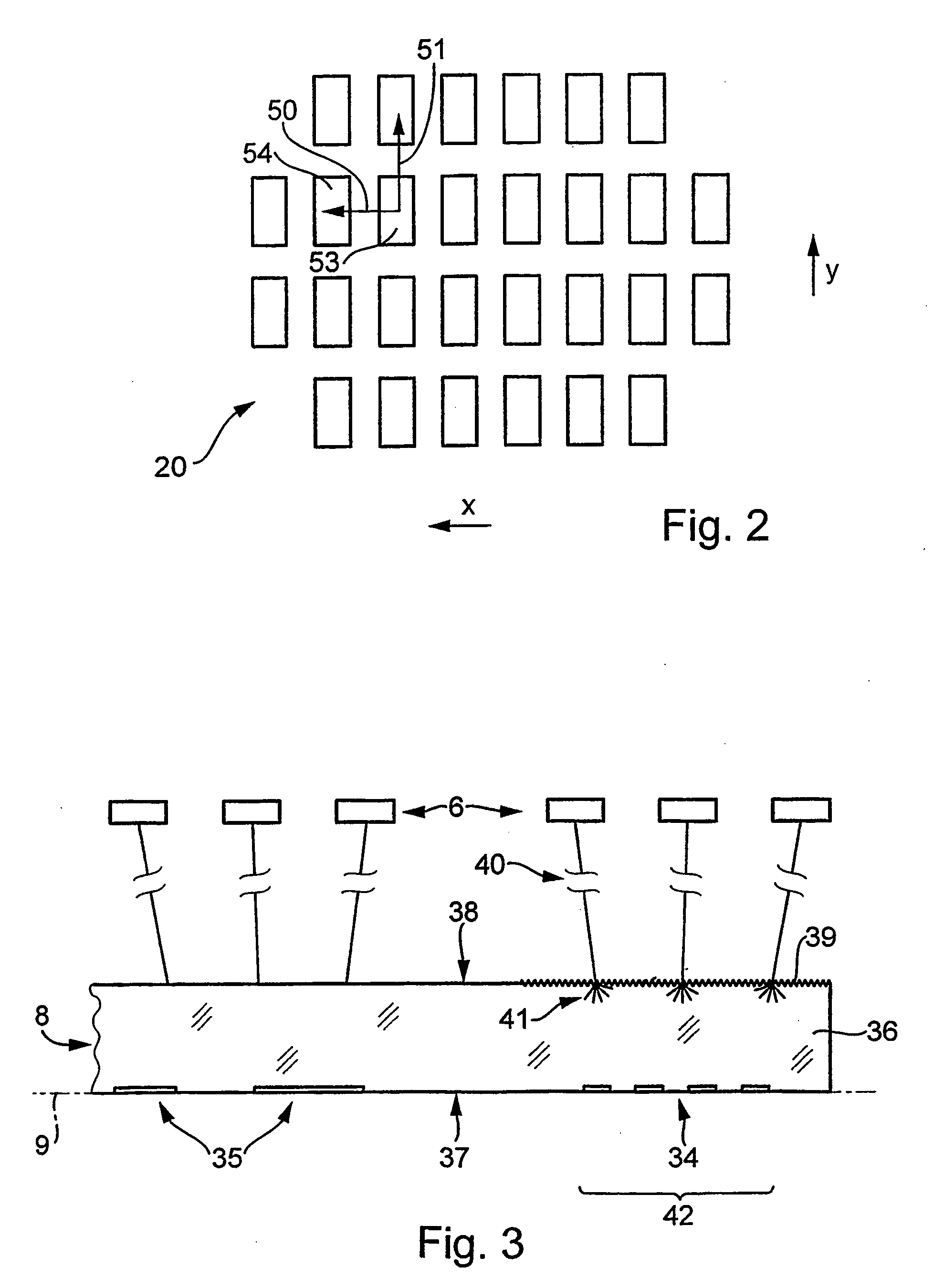
[0021] According to a development, provision is made for the
mask, in at least one region, to have a scattering structure for homogenizing the intensity distribution in the light path of the scattering structure and, if appropriate, for reducing the
spatial coherence of the illuminating light. The scattering structure can bring about a change in the etendue of the
radiation, in that angles of light rays which were previously not present are added and / or the existing
angular distribution is modified. The scattering structure can have a statistical distribution of scattering centers, such as in the case of a matt disk. It is also possible for there to be regularly distributed scattering centers, for example in the form of crossed cylindrical lenses. These can be irregular or regular structures which, for example, are produced by
etching or another surface-roughening treatment. In addition, computer-generated holograms (CGH) are also possible as scattering structures. Scattering structures on the reticle can make it possible, for example, to measure an imaging system at its full
numerical aperture, even if the illumination system connected upstream has a smaller
numerical aperture. With the aid of the scattering, in this case otherwise unexposed regions of the
pupil can also be illuminated. In this way, scattering structures between illumination system and system to be measured can have an enabling effect as a result of introducing further angles.
[0027] Given adequate lateral extent of the parcels or of the regions of
high intensity in the
pupil plane of the imaging system, it can also be beneficial to set a shearing distance which is small as compared with the extent of the parcels. As a result, two or more points within an intensity maximum of the illumination intensity can be compared largely free of intensity and modulation fluctuations.


