Honeycomb structure

a honeycomb and structure technology, applied in the direction of metal/metal-oxide/metal-hydroxide catalysts, machines/engines, chemical/physical processes, etc., can solve the problems of increased alumina layer thickness, increased contact probability, and increased pressure loss, so as to improve the strength against thermal shock and the effect of highly dispersed catalyst components

Inactive Publication Date: 2005-12-01
IBIDEN CO LTD
View PDF26 Cites 146 Cited by
  • Summary
  • Abstract
  • Description
  • Claims
  • Application Information

AI Technical Summary

Benefits of technology

[0024] The present invention is to provide a honeycomb structure having improved strength against thermal shock and vibration, as well as highly dispersed catalyst components. DETAILED DESCRIPTION OF THE INVENTION
[0041] The shape of through-holes formed in the porous honeycomb units, although not particularly restricted, may have a cross-section of substantially triangle or substantially hexagon. In such a case, the strength of the porous honeycomb units can be increased, as the strength (for example, the isostatic strength etc.) of the honeycomb structure can be increased without increasing the pressure loss and degrading the performance such as the conversion of exhaust gas. Examples of porous honeycomb units 11 are shown in FIG. 2: in FIG. 2(a) the cross-section of the through-hole 12 is made triangular, and the through-holes 12 having a triangular cross-section are alternatively arranged in up and down orientations; FIG. 2 (b), edges of 4 through-holes 12 having a triangular cross section are faced each other forming a square structure; and in FIG. 2 (c), the honeycomb unit is formed with the through-holes 12 having a hexagonal cross-section. As shown above, the through-holes 12 may be formed in the porous honeycomb units 11.

Problems solved by technology

However, a simple increase of the supported amount of the material having the high specific surface area such as activated alumina causes an increase of alumina layer thickness or leads to disadvantage that the contact probability is not increased or a pressure loss becomes too large.
However, conventional techniques described above have the following problems.
However, their specific surface area is not large enough to sufficiently disperse catalyst metals and the exhaust gas conversion performance after thermal aging was insufficient.
However, noble metals such as platinum are very expensive and limited precious resources.
In addition, when the honeycomb structures are installed in an automobile, the space is tightly limited.
For these reasons, either could not be appropriate measures.
However, base material such as alumina can not be sufficiently sintered for the sake of keeping specific surface area, and is very weak in strength.
And, as described above, when it is installed in an automobile, the installation space is tightly limited.
Due to large thermal expansion coefficients, cracks caused by thermal stresses can easily occur in the base material such as alumina during sintering (calcination) or during usage.
In view of these, the conventional honeycomb structure has such problems that, when used in an automobile, it can be easily broken and it can neither maintain its shape as a honeycomb structure nor perform a function as a catalyst carrier, since the thermal stress owing to rapid temperature changes and the external force such as large vibrations are exerted on it during usage.
However, the catalyst carrier also has such problems that, when used under the thermal stress owing to rapid temperature changes and the external force such as large vibrations exerted, it can be easily broken and it can neither maintain its shape as a honeycomb structure nor perform a function as a catalyst carrier.

Method used


Image

  • Honeycomb structure
  • Honeycomb structure
  • Honeycomb structure

Examples


example 1

[0072] The procedure mixed 40% weight of γ-alumina particles (the averaged particle diameter of 2 μm), 10% by weight of silica-alumina fibers (averaged fiber diameter of 10 μm, averaged fiber length of 100 μm, and aspect ratio of 10), and 50% by weight of silica sol (solid concentration of 30% by weight). The process added 6 parts by weight of methyl cellulose as an organic binder, small amounts of a plasticizer and a lubricant to 100 parts by weight of the obtained mixture, then mixed and kneaded the whole mixed composition. The mixed composition was extrusion molded by an extruder to a raw molded object.

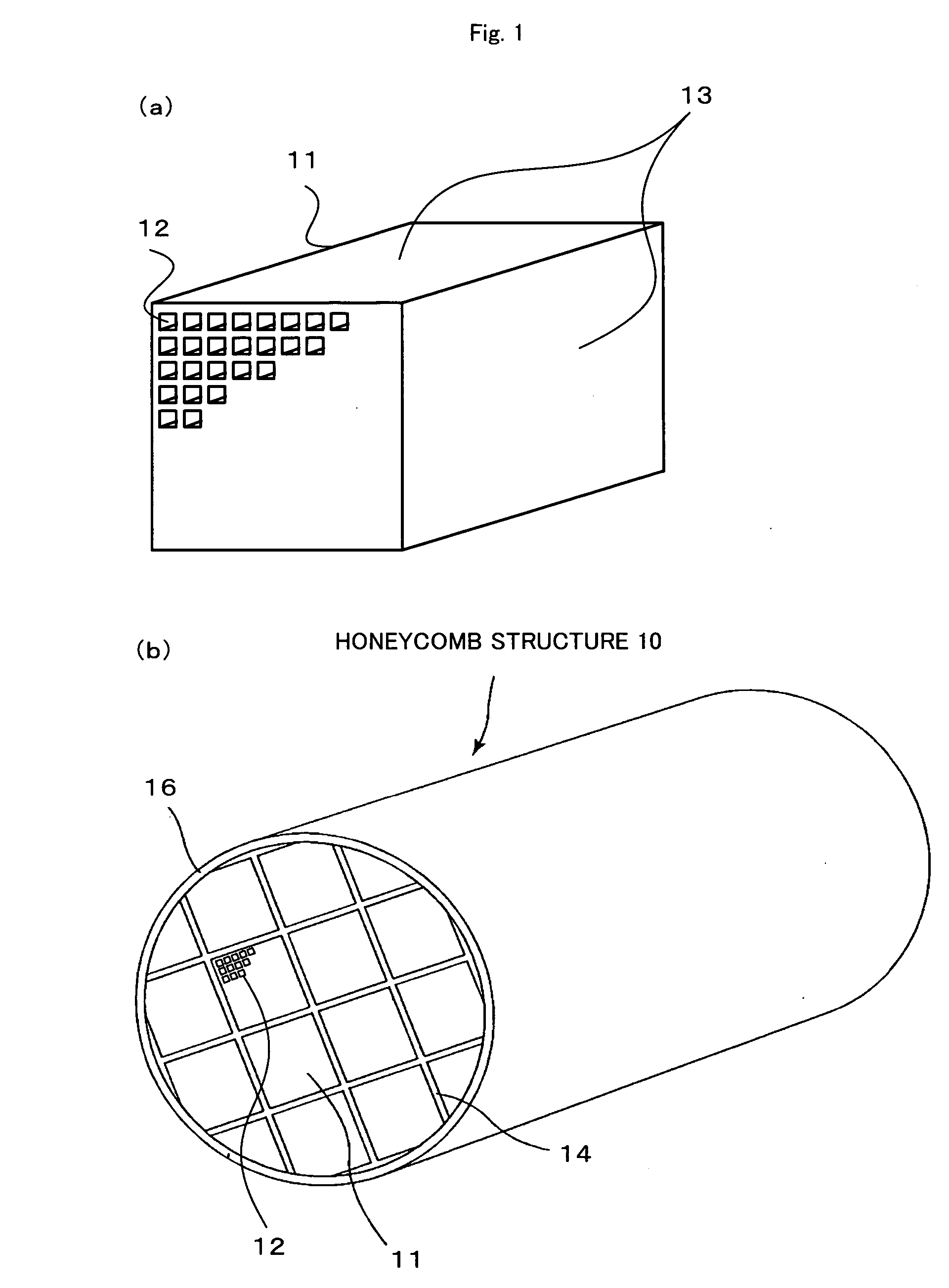
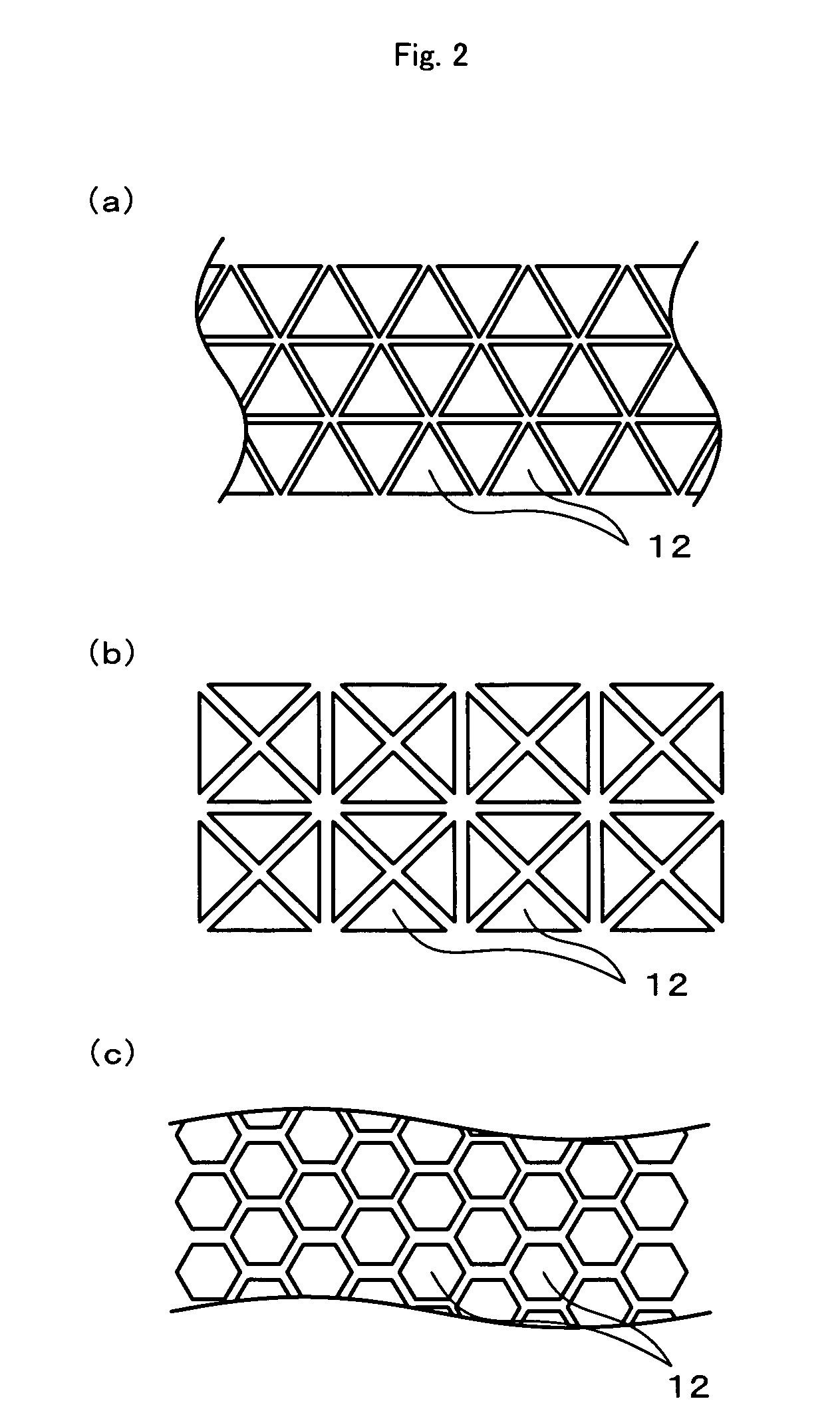
[0073] The raw molded object was sufficiently dried with a microwave dryer and a hot-air dryer, and kept at 400° C. for 2 hours for degreasing. The degreased molded object was sintered at 800° C. for 2 hours to give a porous honeycomb unit 11 of a square pillar (34.3 mm×34.3 mm×150 mm), which has cell density of 93 cells / cm2 (600 cpsi), wall thickness of 0.2 mm, and cell shape of ...

examples 2 to 7

[0076] Honeycomb structures 10 were prepared in the same manner as Example 1, except that the porous honecomb units were designed to have the shape shown in the table of FIG. 4, The shapes of the jointed object of Examples 2, 3, and 4 are respectively illustrated in FIGS. 7 (b), (c), and (d), and the shapes of the jointed object of Examples 5, 6, and 7 are respectively illustrated in FIGS. 8 (a), (b), and (c). In Example 7, since the honeycomb structure 10 was molded as an integral body, the jointing process and cutting process were not performed.

examples 8 to 14

[0077] Porous honeycomb units 11 were prepared in the same manner as Example 1, except that titania particles (averaged particle diameter of 2 μm) were used as the ceramic particle of the inorganic material of the first form and that the porous honeycomb units were designed to have the shape shown in the table of FIG. 4. Subsequently, honeycomb structures 10 were prepared in the same manner as Example 1, except that titania particles (averaged particle diameter of 2 μm) were used as the ceramic particles of the sealing material layer and the coating material layer. Note that the shapes of the jointed objects of Examples 8 to 11 are respectively the same as those shown in FIGS. 7 (a) to (d), and the shapes of the jointed objects of Examples 12 to 14 are respectively the same as those shown in FIGS. 8(a) to (c). The honeycomb structure of Example 14 was molded as an integral body.


PUM

PropertyMeasurementUnit
cross-sectional areaaaaaaaaaaa
aspect ratioaaaaaaaaaa
cross-sectional areaaaaaaaaaaa

Abstract

A honeycomb structure 10 of the present invention comprises: porous honeycomb units 11 having multiple through-holes, including the first form of an inorganic material (for example, ceramic particles), the second form of an inorganic material (for example, inorganic fibers or ceramic particles having large particle sizes), and an inorganic binder; and sealing material layers 14 jointing the porous honeycomb units 11 at outer surfaces 13 where the through-holes are not open. The cross-sectional area perpendicular to the through-holes is about 5 to about 50 cm2. The ratio of the total cross-sectional area of the porous honeycomb units 11 to the cross-sectional area of the honeycomb structure 10 is not less than about 85%. The honeycomb structure 10 reduces thermal stress or vibration applied to each porous honeycomb unit 11, by the sealing material layers 14, and allows for amore effective use of surface on which catalyst components are dispersed.

Description

CROSS REFERENCE TO RELATED APPLICATION [0001] This is a continuation of Application No. PCT / JP2005 / 018866, filed on Dec. 10, 2004, now abandoned.BACKGROUND ART [0002] 1. Technical Field [0003] The present invention relates to a honeycomb structure. [0004] 2. Prior Art to be Disclosed [0005] Conventionally, honeycomb catalysts generally used for conversion of automobile exhaust gases have been produced by supporting a material having a high specific surface area such as activated alumina and a catalyst metal such as platinum on the surface of a cordierite honeycomb structure having an integral structure and low thermal expansion. In addition, it also supports alkaline-earth metals such as Ba for NOx treatment as a NOx occlusion substance under oxygen excessive atmosphere in a lean-burn engine, a diesel engine and the like. In order to improve conversion performance, the carrier need to have a higher specific surface area and particles of noble metals need to be smaller in size and hi...

Claims


Application Information

Patent Timeline
Patent Type & Authority Applications(United States)
IPC IPC(8): F01N3/10B01D46/24B01D53/86B01J23/42B01J35/04C04B35/111C04B35/16C04B35/18C04B35/195C04B35/48C04B35/80C04B38/00C04B41/85F01N3/28
CPCB01D46/2451Y10T428/24149B01D46/2459B01D46/247B01D46/2474B01D2046/2477B01D2046/2496B01J35/04C04B35/111C04B35/16C04B35/18C04B35/195C04B35/481C04B35/6263C04B35/6303C04B35/6316C04B35/803C04B38/0006C04B2111/0081C04B2235/3206C04B2235/3217C04B2235/3218C04B2235/322C04B2235/3232C04B2235/3244C04B2235/3418C04B2235/3427C04B2235/3445C04B2235/3481C04B2235/5228C04B2235/526C04B2235/5264C04B2235/5436C04B2235/9607B01D46/2455C04B35/80B01D46/2488B01D46/2498B01D46/2478B01D46/2492
Inventor OHNO, KAZUSHIGEKUNIEDA, MASAFUMIOGYU, KAZUTAKE
Owner IBIDEN CO LTD
Why Eureka
Try Eureka