Method and apparatus for pumping with a dredge

Inactive Publication Date: 2005-12-08
EDDY PUMP CORP
View PDF6 Cites 60 Cited by
  • Summary
  • Abstract
  • Description
  • Claims
  • Application Information

AI Technical Summary

Benefits of technology

[0016] In accordance with an embodiment of the invention, there is provided a low turbidity head cleaning system which prevents the head from becoming plugged with debris and sticky material and prevents pipeline plugging and a consequential, unavoidable backflow pollution into the water column when the system is shut down and the expensive downtime to unplug the head which is done manually. This is achieved in this embodiment by a cone-shaped, rotatable head mounted around the outside of the stationary, main suction intake pipe. The rotating head is comprised of spaced support bars and rings which have large, sized openings therebetween. The size of the openings depends on the size of the pump being used and the size of the over-sized material desired to be prevented from entering the intake pipe and plugging the system. The cone-shaped, rotating low turbidity head also distributes the weight of the head system onto the ground. Herein the cone-shaped head is cleaned by fixed cone-type assembly mounted adjacent the head to remove material which maybe stuck between the rings. The low turbidity aspect of the system is a result of having a flexible rubber shroud about the cone that prohibits contaminated material from escaping the area inside the cone except through the suction pipe.
[0017] In accordance with one embodiment of the invention, the dredge is provided with a submersible, walking swing system that moves the suction inlet or intake for the pump through the normal swing cut and replaces the conventional swing cable

Problems solved by technology

Several problems have been encountered which has prevented the widespread removal of contaminated material on the bottom including the turbidity to the water caused by using a conventional drag line and bucket type of dredging removal and the cost of remediation of the dredged material.
This drag line and bucket is not suitable for following the diverse topography of a river bed to remove substantially only the contaminated layer on the top of the diverse topography.
Manifestly, the dredging and pumping of the non-contaminated material involves additional unwanted cost; and moreover, all of the dredged material has to be treated by a remediation process.
This excessive removal of non-contaminated material results in a significantly increased remediation costs because all of the dredged material has to be treated.
Rather than using a line and bucket type of removal for marine environmental remediation, attempts have been made to use hydraulic dredging technology that is less damaging to marine life in the water column than the mechanical technologies using a bucket or the like, but have been unsuccessful.
Typically, because most of the conventional existing hydraulic dredging technology is unable to closely follow the diverse terrain levels found at the remediation site or are unable to remove the layer without exceeding turbidity standards.
As a result of not being able to closely follow the diverse terrain to remove substantially only the contaminated layer, they often either remove too little, leaving some of the contamination behind or they significantly over-dredge and take too much of the uncontaminated material.
One of the problems involved in dredging harbor bottoms or other bottoms in a liquid is that the slurry often becomes so

Method used


Image

  • Method and apparatus for pumping with a dredge
  • Method and apparatus for pumping with a dredge
  • Method and apparatus for pumping with a dredge

Examples


Embodiment Construction

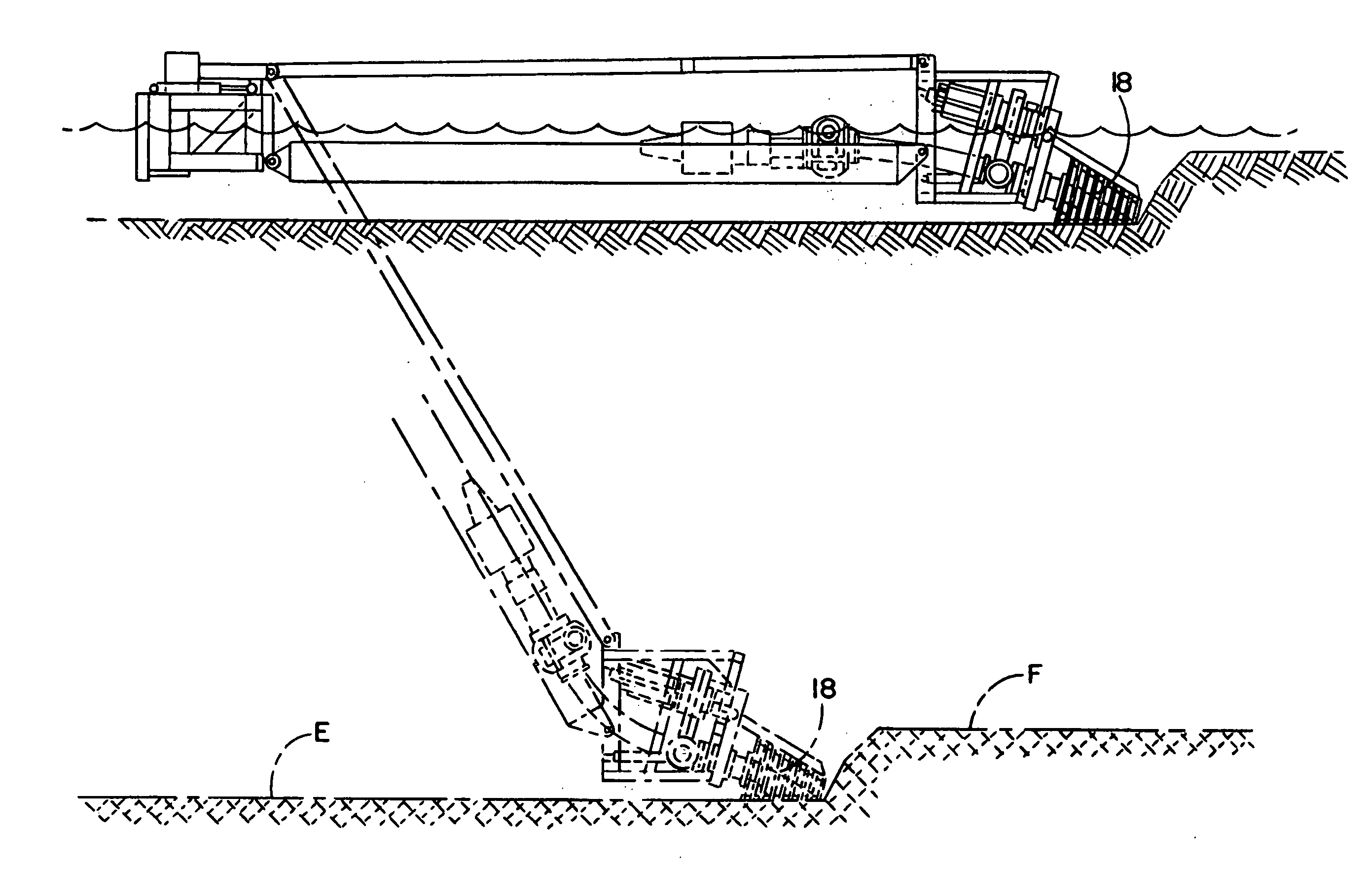
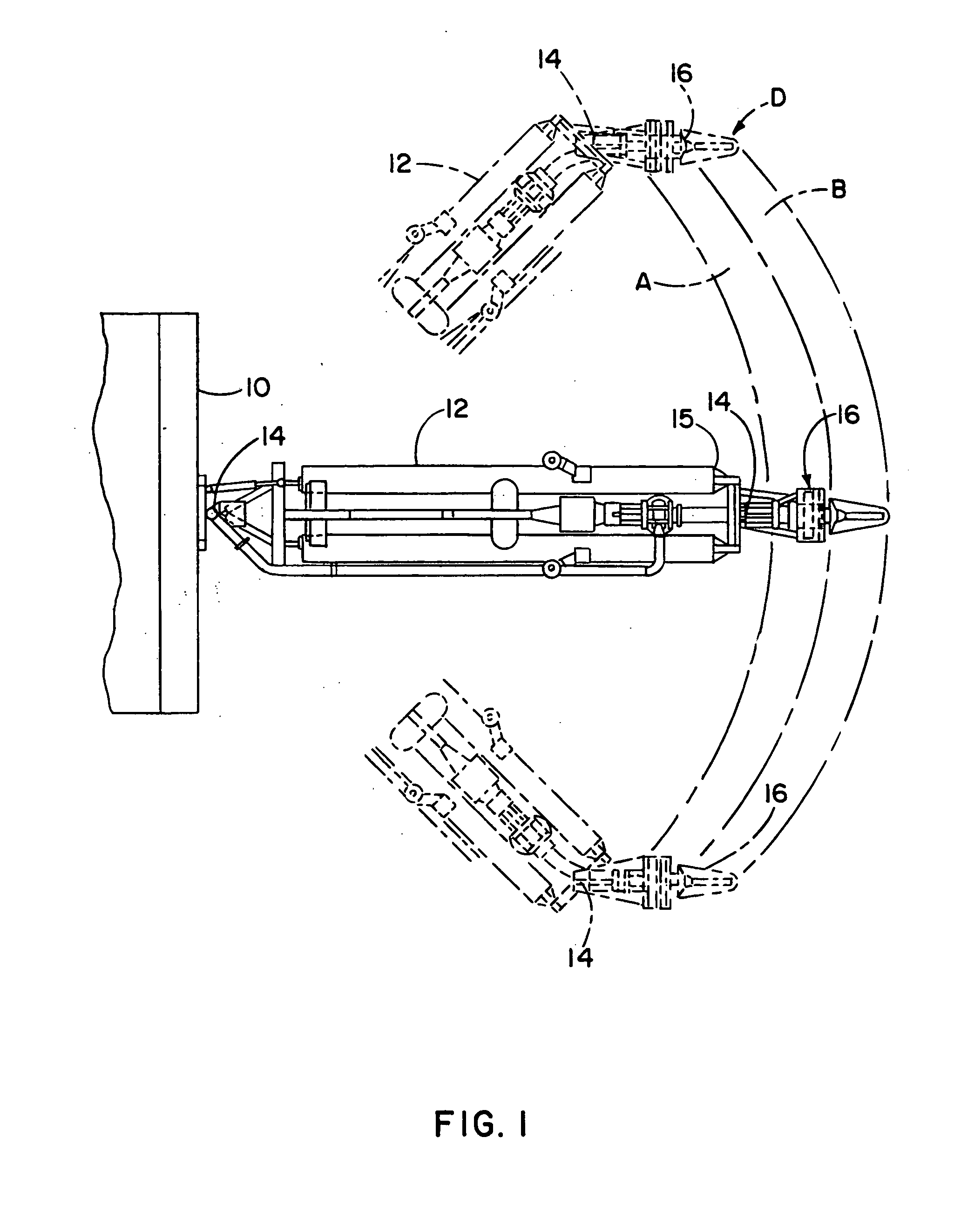
[0034] As shown in the drawings and in particularly in FIG. 1, there is a first embodiment which comprises a dredge 10 having an articulated or swingable boom 12 which pivots about a pivot mounting 14 with the dredge, which is usually a floating barge or the like. A suction head 16 extends into and is submersed at its lower end in the water. The suction head is mounted on a forward or distal end 15 of the boom and has an intake 18 for intaking material from the submerged bottom as shown in FIG. 2. The illustrated head 16 is also articulated or pivotally mounted at a pivot mounting 20 to the distal end 15 of the boom. As best seen in FIG. 1 the suction head takes a arcuate cut shown by arrow A for a first cut which is then followed by a second cut B between opposite swing points or ends of the arcuate edge C and D in FIG. 1.

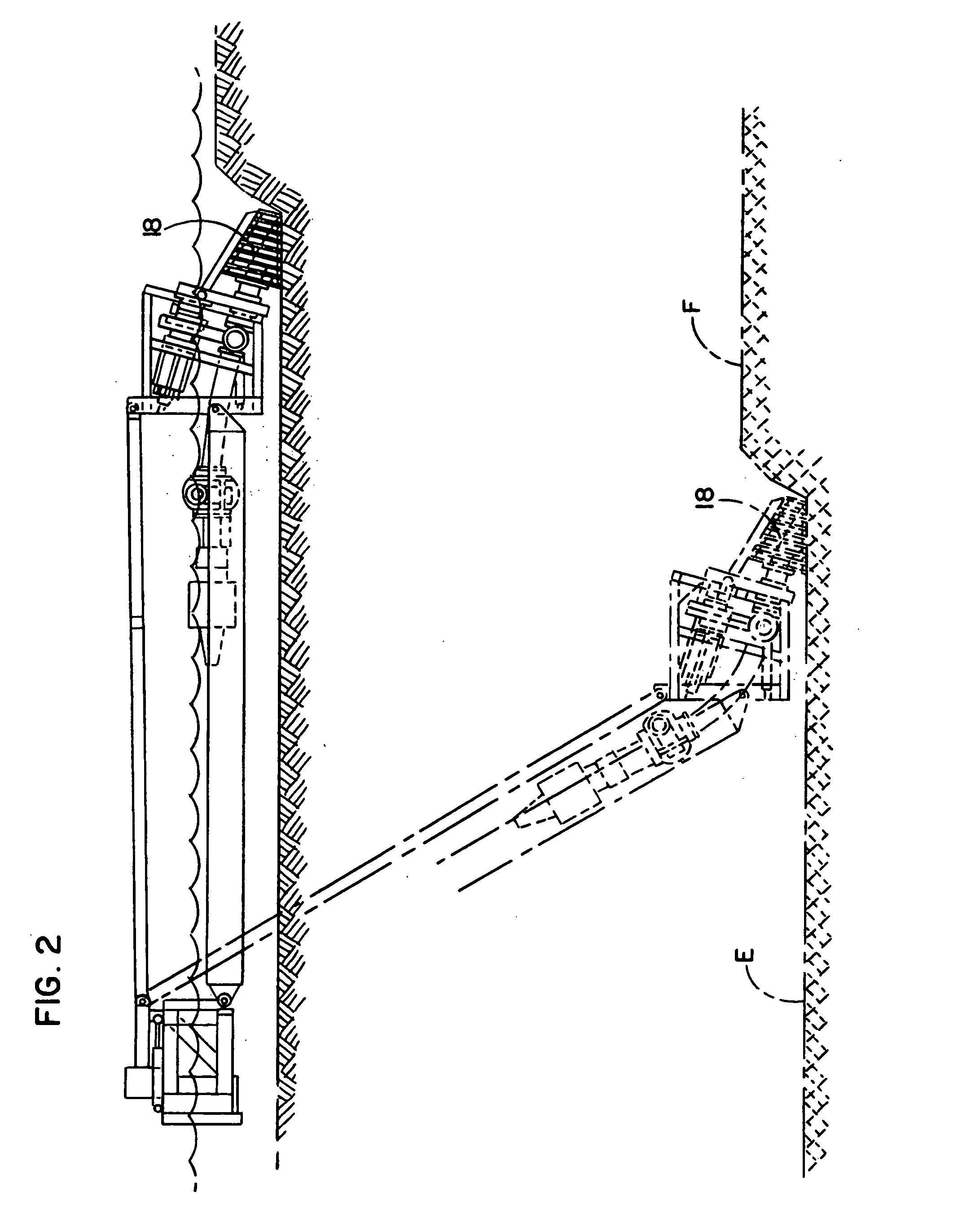
[0035] Referring to FIG. 2, the head intake 18 is shown at a lower level E having lowered a harbor bottom 22 at the cut shown in FIG. 2 from the higher elevation...


PUM


Abstract

A system usable for dredging may include a suction bypass system for automatically maintaining a sufficiently high, liquid flow velocity. Preferably, a flow sensor monitors flow velocity and when the monitor flow decreases to an extent that plugging may occur, a liquid bypass valve is opened and an intake line valve is closed until the flow velocity increases whereupon the valves are returned to their original positions. An automatic level cut removes a relatively constant layer of material from a contoured bottom. The illustrated automatic level cut process comprises adjusting the force with which the suction head engages the bottom, moving the suction head in a direction opposite to the direction of the swing of the boom to keep the suction head pointing straight ahead, and maintaining the suction head to stay substantially level with the bottom even though the angle of the boom increases to the surface of the water body. A leveling device comprising a parallelogram linkage may be used to maintain the suction head substantially level with the bottom. A predetermined amount of load force may be applied by the head against the bottom. Herein, a winch and cable and the controller are operated to lift some of the head weight until the desired predetermined head force is applied to the bottom. A walking system moves the pipe intake for taking a sideways cut without the use of a spud pole, anchors and anchor lines. Large blade members or feet travels in an endless path with the feet entering the bottom while vertically disposed and remained disposed vertically while entering and leaving the bottom so as not to dig or stir the bottom that will cause large liquid turbidity. A low turbidity head cleaning system prevents the head from being plugged and debris or sticky material. Preferably, a rotatable cone-shaped head is provided with spaced rings and bars that define sized openings that limit the size of debris entering into the intake. A fixed comb removes material stuck on the rotating head. A shroud has an open bottom side thereby preventing bottom material from escaping and increasing with turbidity. A suction head articulation system keeps the head pointed in the forward direction of dredge advancement to create a smooth finish grade.

Description

[0001] This invention relates to a dredge pumping system for dredging material from the bottom using an articulated head and a suction pump to cause a mixture of material and liquid to flow into a suction inlet and a pipe and through the pump for later discharge. BACKGROUND OF THE INVENTION [0002] Many rivers and harbors have contaminated materials on the bottom of the water body usually in a layer. It is desirable to remove this layer and to remediate the contaminated hazardous waste material in this layer by various technologies. Several problems have been encountered which has prevented the widespread removal of contaminated material on the bottom including the turbidity to the water caused by using a conventional drag line and bucket type of dredging removal and the cost of remediation of the dredged material. Often the drag bucket takes a fixed depth of cut, e.g., a three foot depth and leaves a flat bottom. This drag line and bucket is not suitable for following the diverse to...

Claims


Application Information

Patent Timeline
IPC IPC(8): E02F3/88E02F3/90E02F5/28E02F9/04E02F9/14E02F9/20E02F9/26F04D7/04F04D15/00G01F1/00
CPCE02F3/8841F04D15/0005F04D7/045E02F3/907
Inventor WEINRIB, HARRY PETERWAHLGREN, DANIEL K.
Owner EDDY PUMP CORP
Why Eureka
Try Eureka