The agent's intended local effect is equally diluted and
efficacy is compromised.
Thus systemic agent delivery requires higher dosing to achieve the required localized
dose for
efficacy, often resulting in compromised safety due to for example systemic reactions or side effects of the agent as it is delivered and processed elsewhere throughout the body other than at the intended target.
A traumatic event, such as hemorrhage, gastrointestinal fluid loss, or renal fluid loss without proper
fluid replacement may cause the patient to go into ARF.
For example, a reduction in
blood flow and
blood pressure in the kidneys due to reduced
cardiac output can in turn result in the retention of excess fluid in the patient's body, leading, for example, to pulmonary and systemic
edema.
However, many of these drugs, when administered in systemic doses, have undesirable side effects.
Additionally, many of these drugs would not be helpful in treating other causes of ARF.
Surgical device interventions, such as
hemodialysis, however, generally have not been observed to be highly efficacious for long-term management of CHF.
Such interventions would also not be appropriate for many patients with strong hearts suffering from ARF.
For example, the kidneys as one of the body's main
blood filtering tools may suffer damage from exposed to
high density radiopaque contrast dye, such as during coronary, cardiac, or neuro
angiography procedures.
One particularly harmful condition known as “radiocontrast
nephropathy” or “RCN” is often observed during such procedures, wherein an acute impairment of
renal function follows
exposure to such radiographic contrast materials, typically resulting in a rise in serum
creatinine levels of more than 25% above baseline, or an absolute rise of 0.5 mg / dl within 48 hours.
Therefore, in addition to CHF,
renal damage associated with RCN is also a frequently observed cause of ARF.
These physiological parameters, as in the case of CHF, may also be significantly compromised during a surgical intervention such as an
angioplasty, coronary
artery bypass, valve repair or replacement, or other cardiac interventional procedure.
Notwithstanding the clear needs for and benefits that would be gained from such local
drug delivery into the renal system, the ability to do so presents unique challenges as follows.
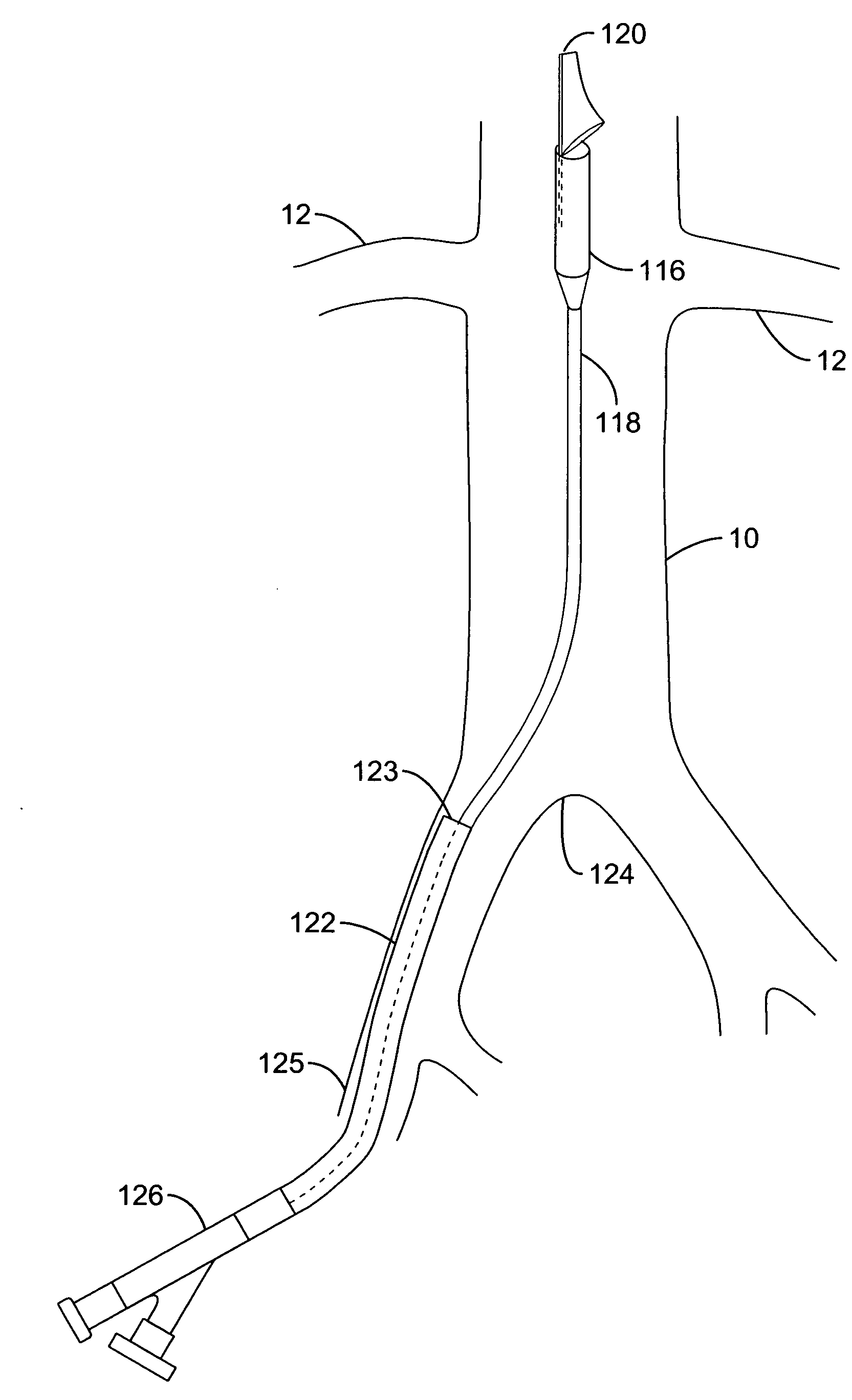
This presents a unique challenge to locally deliver drugs or other agents into the renal system on the whole, which requires both kidneys to be fed through these separate respective arteries via their uniquely positioned and substantially spaced apart ostia.
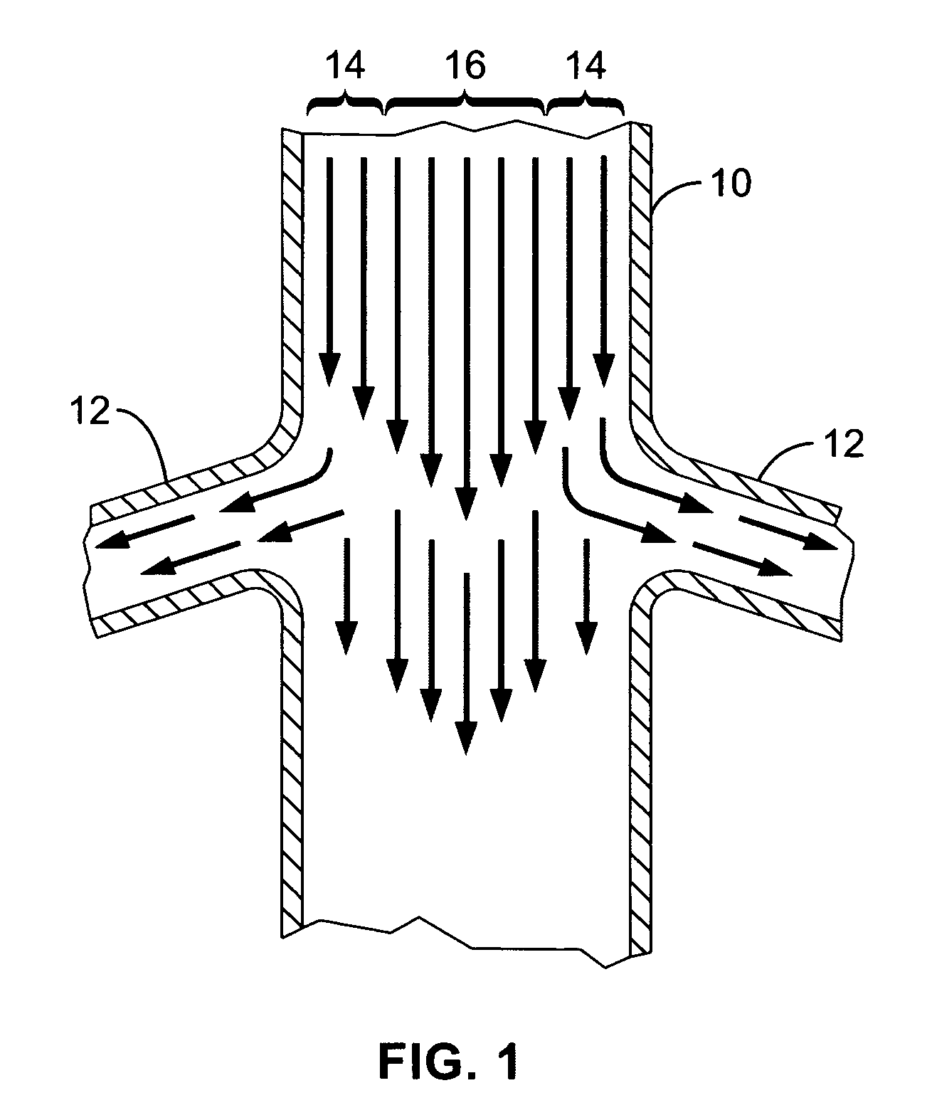
In another regard, mere local delivery of an agent into the natural, physiologic
blood flow path of the
aorta upstream of the kidneys may provide some beneficial, localized renal delivery versus other systemic
delivery methods, but various undesirable results still arise.
This reduces the amount of agent actually perfusing the renal arteries with reduced
efficacy, and thus also produces unwanted loss of the agent into other organs and tissues in the
systemic circulation (with highest concentrations directly flowing into downstream circulation).
However, such a technique may also provide less than completely desirable results.
For example, such seating of the delivery
catheter distal tip within a
renal artery may be difficult to achieve from within the large
diameter / high flow
aorta, and may produce harmful intimal injury within the
artery.
This can become unnecessarily complicated and
time consuming and further compound the risk of unwanted injury from the required
catheter manipulation.
Moreover, multiple dye injections may be required in order to locate the renal ostia for such
catheter positioning, increasing the risks associated with contrast agents on
kidney function (e.g. RCN)—the very
organ system to be protected by the agent
delivery system in the first place.
Still further, the renal arteries themselves, possibly including their ostia, may have pre-existing conditions that either prevent the ability to provide the required catheter seating, or that increase the risks associated with such mechanical intrusion.
In particular, to do so concurrently with
multiple delivery catheters for simultaneous infusion of multiple renal arteries would further require a guide sheath of such significant dimensions that the preferred Seldinger
vascular access technique would likely not be available, instead requiring the less desirable “
cut-down” technique.
However, the flow to lower extremities downstream from such
balloon system can be severely occluded during portions of this counterpulsing cycle.
Moreover, such previously disclosed systems generally lack the ability to deliver
drug or agent to the
branch arteries while allowing continuous and substantial downstream
perfusion sufficient to prevent unwanted
ischemia.
Notwithstanding the interest and advances toward locally delivering agents for treatment or diagnosis of organs or tissues, the previously disclosed systems and methods summarized immediately above generally lack the ability to effectively deliver agents from within a main
artery and locally into substantially only
branch arteries extending therefrom while allowing the passage of substantial
blood flow and / or other medical devices through the main artery past the branches.
This is in particular the case with previously disclosed renal treatment and diagnostic devices and methods, which do not adequately provide for local delivery of agents into the renal system from a location within the aorta while allowing substantial blood flow continuously downstream past the renal ostia and / or while allowing distal
medical device assemblies to be passed retrogradedly across the renal ostia for upstream use.

