Eureka AIR delivers breakthrough ideas for toughest innovation challenges, trusted by R&D personnel around the world.

Method and device for wave-front sensing

Inactive Publication Date: 2006-02-16
MAX PLANCK GESELLSCHAFT ZUR FOERDERUNG DER WISSENSCHAFTEN EV
View PDF10 Cites 46 Cited by
  • Summary
  • Abstract
  • Description
  • Claims
  • Application Information

AI Technical Summary

Benefits of technology

[0029] Preferably, the present imaging method is implemented as a fluorescence microscopy method, i.e. fluorescence is excited with the adapted illumination light at the respective focal points. The combination of wave-front sensing of backscattered light with the image sampling on the basis of fluorescence light represents an essential advantage of the present invention. The wave-front sensing can be implemented with a low illumination intensity which does not bleach the specimen. Another important advantage is obtained as the fluorescence can be linearly excited as in the conventional confocal microscopy, or non-linearly exited as in the conventional multi-photon excitation microscopy. Accordingly, the invention can be combined without problem with available fluorescence microscopy methods.
[0030] According to a third general aspect of the invention, a wavefront sensing device is provided with an optical splitting device being arranged for splitting illumination light into a sample light path for focussed illumination and detection of specimen light as well as into a reference light path for forming a time-gate for sample light from a predetermined sample plane. Furthermore, the wave-front sensing device of the invention comprises a detector device with two-dimensional sensitivity and an evaluation device being connected with the detector device for reconstructing the wave-front of the sample light detected. The provision of the reference light path is advantageous in terms of time-based or coherence-based filtering of the specimen light allowing a direct measurement of the wave-front as outlined above. In contrast to conventional optical setups, the device of the present invention directly provides a quantitative representation of the wave-front.
[0031] Preferably, the illumination light is provided with a laser light source (pulse laser) generating laser pulses.
[0032] According to a preferred embodiment of the invention, at least one of the sample and reference light paths has an adjustable optical path length advantageously allowing the selection of the sample plane in the specimen.
[0033] Preferably, the sample and reference light paths form an interferometer being arranged for a superposition of the reference light and the specimen light at the detector device. Alternatively, the reference light path may be used for directing a switching light pulse to a light shutter being operated on the basis of the Kerr effect.
[0034] According to a fourth general aspect of the invention, an imaging device (microscope) for microscopic imaging a specimen is proposed which comprises the wave-front sensing device according to the invention as well as a wave-front corrector device arranged in the sample light pulse.

Problems solved by technology

In practice, diffraction limited resolution is often not achievable due to distortions of the wave-front introduced by refractive index inhomogeneities in the specimen.
An analogue problem is present in astronomy where wave-front distortions may be caused by refractive index variations due to turbulences in the atmosphere.
In microscopy, the adaptation technique known from infrared astronomy generally cannot be applied since neither natural nor artificial “guide stars” are available in a specimen like e.g. a biological specimen.
As an example, in a biological specimen a blood vessel may lie between a focal region of interest and a surface of the specimen causing an essential distortion of the light to be detected.
For these less favourable biological specimens, wave-front measuring techniques from astronomy cannot be directly applied.
However, these conventional procedures have the following disadvantages.
Secondly, the iterative wave-front optimization requires the presence of a sufficiently bright fluorescence signal.
Therefore, samples with sensitive fluorophores cannot be investigated due to photo bleaching.
Furthermore, the iterative optimization is only feasible if the search space is sufficiently low dimensional, which limits the order to which distortion can be corrected.
A further disadvantages is related to the high time consumption of the search algorithm using the deformable mirror.
The fluorescence measurement represents an essential disadvantage with regard to the investigation of sensitive samples.

Method used


Image

  • Method and device for wave-front sensing
  • Method and device for wave-front sensing
  • Method and device for wave-front sensing

Examples


Embodiment Construction

1. Optical Setup of a Wave-Front Sensing Device

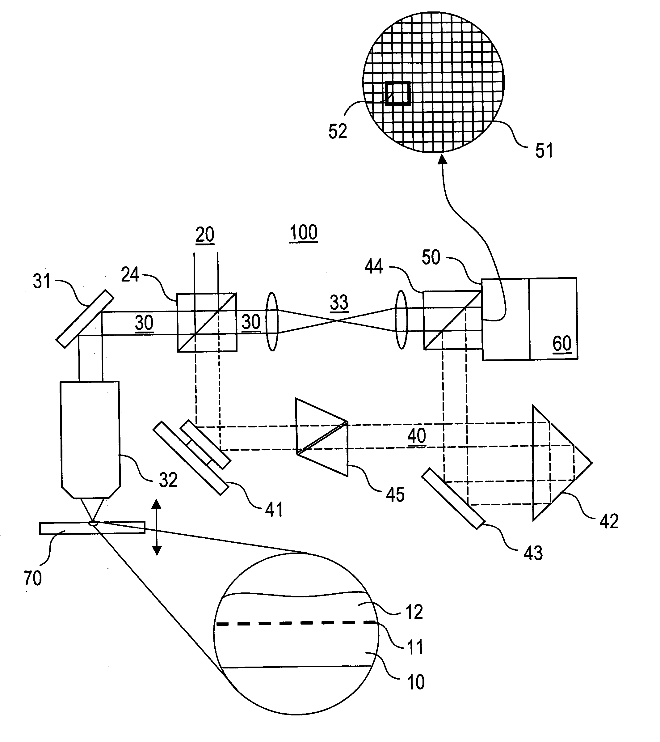
[0040] According to the embodiment illustrated in FIG. 1, the wave-front sensing device 100 of the present invention comprises an illumination light path 20, which is split at the beam splitter cube 24 into the sample light path 30 and the reference light path 40.

[0041] The illumination light path 20 includes a laser light source and optical components, which are shown with further details in FIG. 3. The laser light source is a Ti:sapphire laser (Coherent Mira, centre wavelength 915 nm) emitting horizontally polarized light pulses with a pulse duration of about 100 fs. The beam splitter cube 24 is a non-polarizing 50:50 splitter (BK 7, Coherent, Inc.).

[0042] The sample light path 30 extends from the beam splitter cube 24 via a deflection mirror 31 and a focussing optic 32 to the specimen 10 and in opposite direction from the specimen 10 via the focussing optic 32, the mirror 31, the beam splitter cube 24, an imaging optic 33 and a b...


PUM


Abstract

A method for sensing a wave-front of specimen light scattered from an illuminated area in a specimen (10) includes the steps of focusing illumination light into the specimen (10), directing specimen light scattered in the specimen (10) to a detector device (50) having a plurality of detector elements (51) and being capable to sense light with local resolution, detecting sample light contained in the specimen light with the detector device (50), said sample light being scattered in a predetermined sample plane (11) of the specimen (10) and being selected by a time-based gating of the specimen light, locally resolved measuring phase information of the sample light, and reconstructing the wave-front of the sample light on the basis of the phase information. Furthermore, a method of microscopic imaging with adapted illumination light is described.

Description

SUBJECT OF THE INVENTION [0001] The present invention relates to methods and devices for sensing the wave-front of light scattered in a specimen. Furthermore, the invention relates to methods and devices for imaging a specimen, in particular to microscopy methods and devices using illumination light with an adapted wave-front. BACKGROUND OF THE INVENTION [0002] An important goal of in-vivo microscopy is diffraction limited imaging from layers deep within biological specimens. In practice, diffraction limited resolution is often not achievable due to distortions of the wave-front introduced by refractive index inhomogeneities in the specimen. [0003] An analogue problem is present in astronomy where wave-front distortions may be caused by refractive index variations due to turbulences in the atmosphere. These distortions are routinely corrected using adaptive optics (see F. Merkle et al. “Successful Tests of Adaptive Optics” in “ESO messenger”, vol. 58, 1989, pages 1-4). Adaptive wave...

Claims


Application Information

Patent Timeline
IPC IPC(8): G01B9/02
CPCG01J9/00G01J9/02G03H2001/0467G03H2001/0458G03H1/0443G01N21/6458
Inventor FEIERABEND, MARCUSRUCKEL, MARKUSDENK, WINFRIED
Owner MAX PLANCK GESELLSCHAFT ZUR FOERDERUNG DER WISSENSCHAFTEN EV
Why Eureka
Eureka Blog
Learn More