High efficiency wavelength converters

a wavelength converter and high-efficiency technology, applied in the field of high-efficiency wavelength converters, can solve the problems of low conversion efficiency, inability to achieve true phase locking, and inability to allow optimal mode overlap, so as to improve the conversion efficiency of the device, increase the symmetry of the waveguide refractive index profile, and increase the overlap

Inactive Publication Date: 2006-03-02
HC PHOTONICS
View PDF14 Cites 3 Cited by
  • Summary
  • Abstract
  • Description
  • Claims
  • Application Information

AI Technical Summary

Benefits of technology

[0035] This method, which can be found discussed in “Reverse Exchange Method For Burying Proton Exchanged Waveguides,” J. L. Jackel and J. J. Johnson, Electronics Letters, 18 Jul. 1991, Vo. 27, No. 15, produces a more symmetric waveguide refractive index profile than is provided by prior art methods and the increased symmetry increases the overlap between the fundamental mode of the incident radiation and the second harmonic produced by the non-linearity of the QPM crystal for radiation substantially confined within the waveguide. Accordingly, the conversion efficiency of the device is improved and the beam profile of the emergent beam is rendered more symmetric. The symmetry of the waveguide formation is produced by the restoration of the initial H+ concentration and index of refraction of the crystal near the crystal surface by the RPE process, which adds Li+ near the surface by means of the addition of the RPE solution (possible c

Problems solved by technology

Note that 2k1−k2 is not zero because of the dispersion of the material, so true phase locking is generally not possible.
Although QPM improves the conversion efficiency of the crystal material, there is still a significant problem associated with the necessity of having the incident (pumping) radiation propagate in a tightly focused beam to provide adequate power density within the region of wave overlap.
In bulk material, the pumping beam cannot be tightly focused since the propagation wave will diffract, therefore it is usually weakly focused, resulting in low conversion efficiency.
Such methods lead to questionable results, particularly when doped ferroelectric materials are used.
The resulting two-s

Method used


Image

  • High efficiency wavelength converters
  • High efficiency wavelength converters
  • High efficiency wavelength converters

Examples


Embodiment Construction

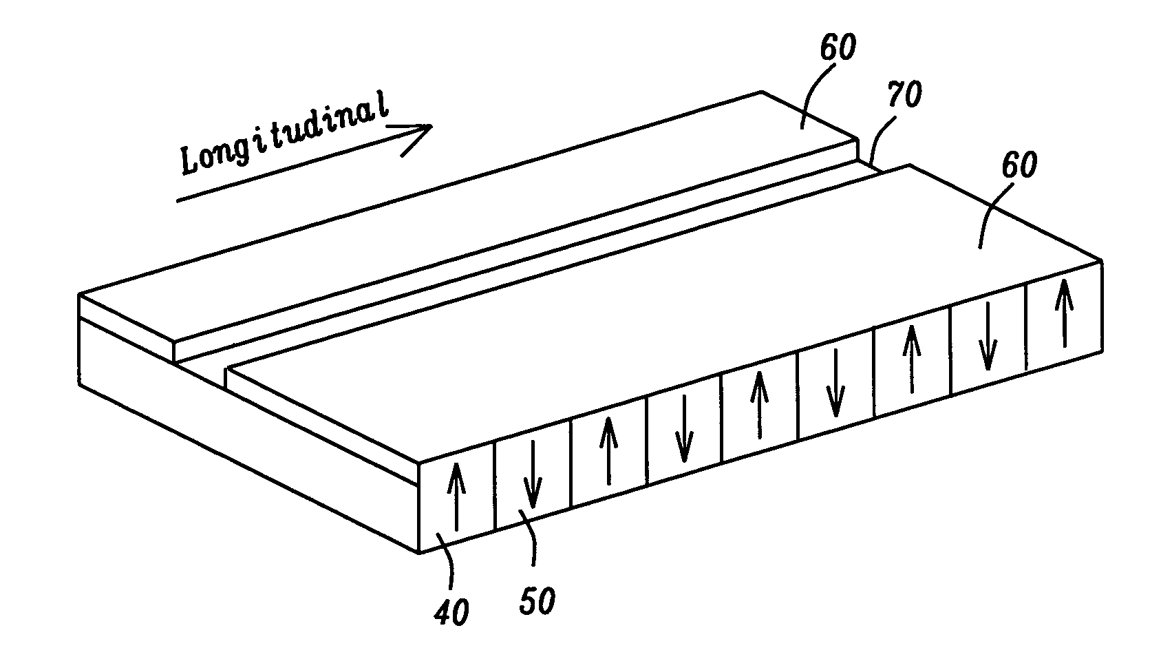
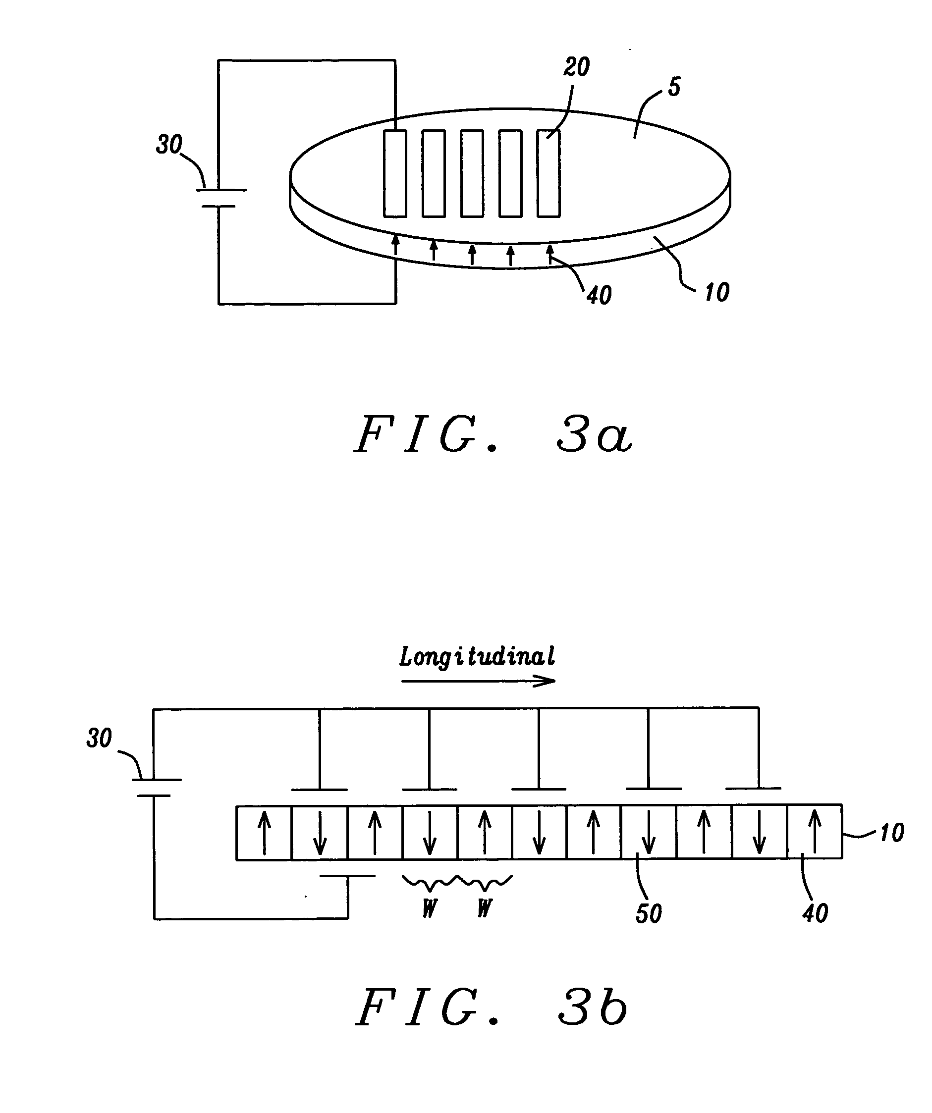
[0044] The preferred embodiments of the present invention teach a method of forming a buried waveguide having a symmetric refractive index profile within a periodically domain reversed nonlinear ferroelectric crystal without damaging the optical properties of the crystal. The symmetric form of the waveguide index profile allows the input and polarization waves to overlap for an efficient energy transfer and promotes an optimal cross-section of the output wave. The resulting device can be advantageously used for a wide range of optical wavelength processing, including optical frequency conversion.

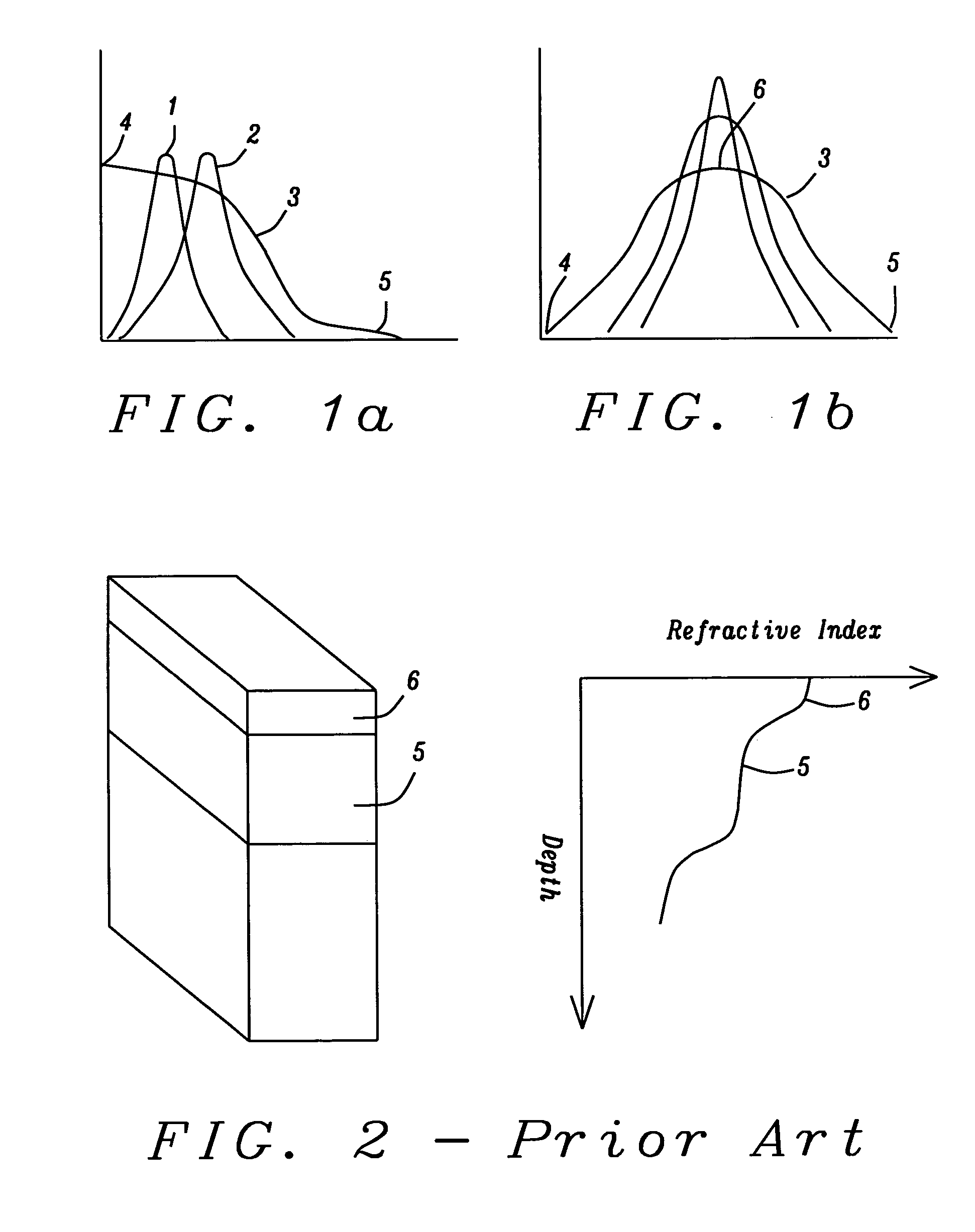
[0045] Referring first to FIG. 1a, there is shown an example of poor overlap between two modes within a waveguide region, a fundamental input radiation mode (1) and a resulting mode produced by the nonlinear response of the crystal (2). The poor overlap is a result of the non-symmetric refractive index profile (3) of the waveguide region, which is highest at the crystal surface (4) and lowe...


PUM


Abstract

A method is provided for forming a waveguide region within a periodically domain reversed ferroelectric crystal wherein the waveguide region has a refractive index profile that is vertically and horizontally symmetric. The symmetric profile produces effective overlapping between quasi-phasematched waves, a corresponding high rate of energy transfer between the waves and a symmetric cross-section of the radiated wave. The symmetric refractive index profile is produced by a method that combines the use of a diluted proton exchange medium at a high temperature which produces a region of high index relatively deeply beneath the crystal surface, followed by a reversed proton exchange which restores the original crystal index of refraction immediately beneath the crystal surface.

Description

BACKGROUND OF THE INVENTION [0001] 1. Field of the Invention [0002] This invention relates to the fabrication of high efficiency wavelength converters and their application in the field of nonlinear optical frequency conversion. [0003] 2. Description of the Related Art [0004] Nonlinear frequency conversion provides a valuable tool for the generation of laser radiation in spectral ranges that are difficult if not impossible to obtain by conventional laser sources. Ferroelectric crystals (crystals having nonlinear polarizations) such as LiNbO3 or LiTaO3 or such crystals doped with MgO or ZnO are attractive candidates for use in such applications. Early attempts to use such crystals as a means for doubling the frequency of an incoming wave of optical radiation have shown that it is necessary to confine the incoming wave within an optical waveguide in order to maximize the conversion efficiency of the doubling process. Umegaki et al. (U.S. Pat. No. 4,820,011) form a waveguide by deposit...

Claims


Application Information

Patent Timeline
IPC IPC(8): G02F1/365
CPCG02F1/3775G02F1/3558
Inventor WU, SHANG-YITSAI, VIVIENCHOU, MING-HSIEN
Owner HC PHOTONICS
Why Eureka
Try Eureka