Tunable fiber laser light source

Active Publication Date: 2006-03-16
SANTEC
View PDF26 Cites 6 Cited by
  • Summary
  • Abstract
  • Description
  • Claims
  • Application Information

AI Technical Summary

Benefits of technology

[0012] According to the present invention, an optical fiber is used as a light path for laser oscillation to thereby extend a length of the light path and change an oscillation wavelength by means of a tunable optical filter. In the tunable filter, an optical beam deflector deflects light and inputs the light to a diffraction grating. The diffraction grating is used as a filter, which changes the wavelength in accordance with an incident angle, and serves to reflect the light in a same direction as the incident light

Problems solved by technology

In such spectral analysis, however, the intensity and density of the light from the light source with respect to the wavelength is low, and those of light which is used in spectral analysis is also low.
Consequently, the light source has a drawback such that even if Fourier transformation is performed, a light signal cannot be detected due to noise, and it is difficult to carry out the analysis.
Therefore, when the wavelength of the tunable filter is simply changed, the output becomes unstable between the longitudinal modes.
Therefore, in order to vary the wavelength continuously in a single mode and to, moreover, make the output stable, the length of the external cavity has to be controlled finely by using such devices as a piezo-element and a complicated control is necessary.
Consequently, the method has a drawback that it is difficult to change the wavelength at high speed.
However, a tunable laser light source capable of performing the high-speed scanning in such a manner as to follow an

Method used


Image

  • Tunable fiber laser light source
  • Tunable fiber laser light source
  • Tunable fiber laser light source

Examples


first embodiment

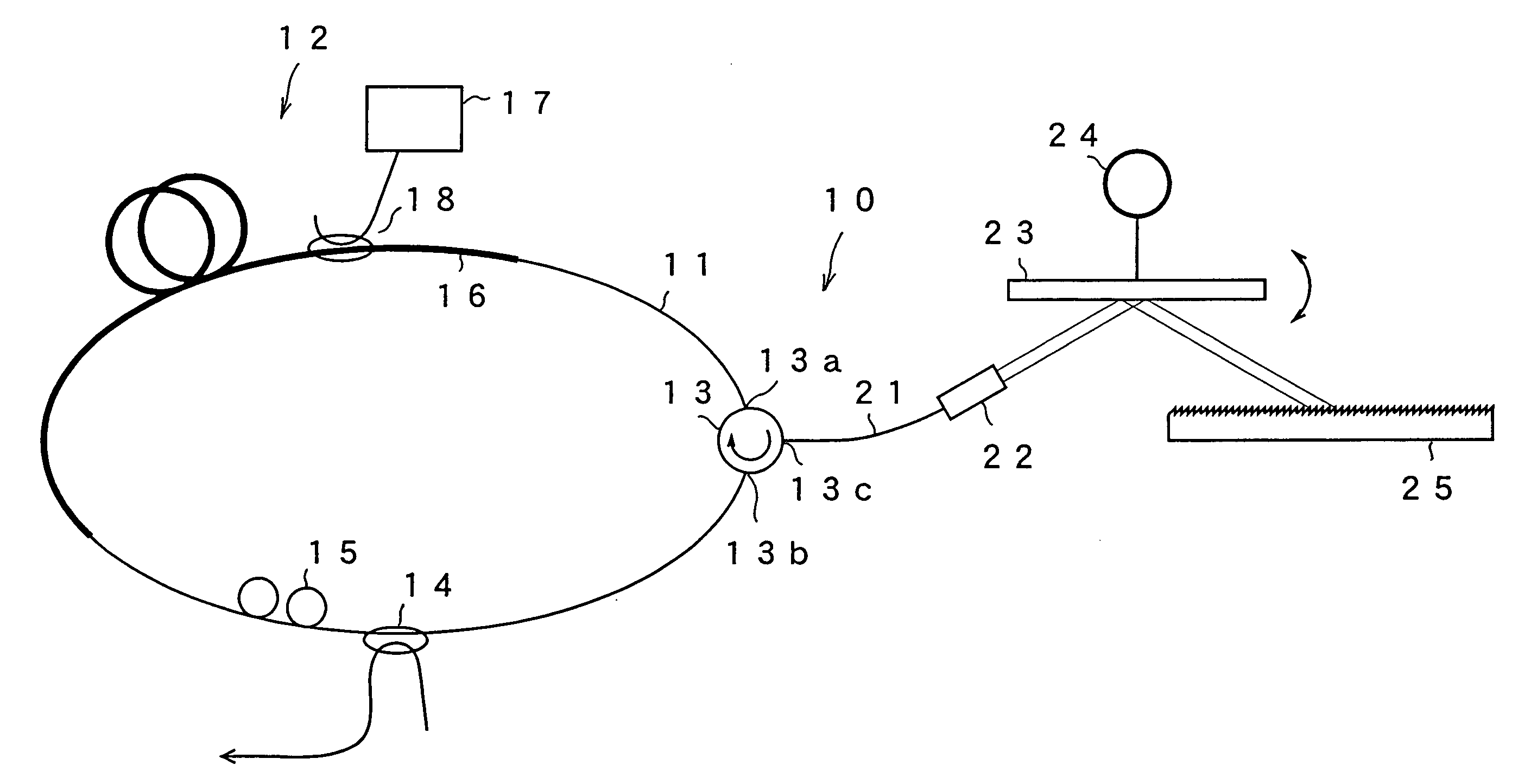
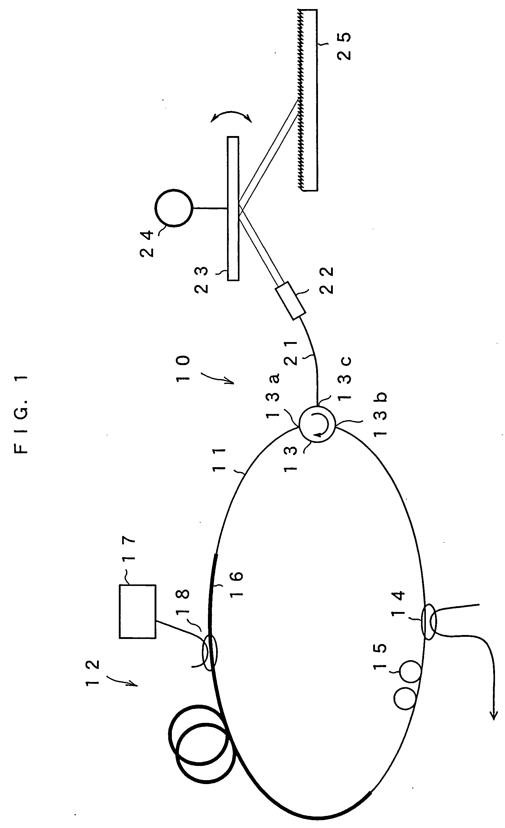
[0029]FIG. 1 is a schematic view showing the configuration of a tunable fiber laser light source according to a first embodiment of the present invention. A tunable fiber laser light source 10 of this embodiment forms a loop by including an optical fiber 11. In a part of the loop, a gain medium 12, an optical circulator 13, an optical coupler 14 and a polarization controller 15 are provided. The gain medium 12 has an erbium doped fiber 16 provided in a part of the optical fiber loop and doped with erbium ions (Er3+), a semiconductor laser 17 for exciting the fiber for emitting pump light to the erbium doped fiber 16, and a WDM coupler 18. The wavelength bandwidth of the gain can be adjusted by selecting a material with which the erbium doped fiber is doped. The optical fiber loop has a length of, for example, 30 to 50 m. The semiconductor laser 17 for exciting has a wavelength of, for example, 1480 nm or 980 nm and amplifies light passing through the erbium doped fiber 16. The optic...

second embodiment

[0038] Next, a second embodiment of the present invention will be described. There is no difference between the present embodiment and the first embodiment in terms of the optical fiber loop, and the structure from the circulator 13 to the optical fiber 21 and collimate lens 22. In the present embodiment, an optical beam diameter of the light emitted from the collimate lens 22 is expended as shown in FIG. 4. When a beam diameter of an optical beam from the collimate lens 22 is W1, the optical beam diameter is enlarged to W2 by a beam expander 31 having a prism shape as shown in FIG. 4. The light reflected in the mirror 23, the optical beam diameter of which is further enlarged to W3 by a beam expander 32, is added to the diffraction grating 25. The optical beam diameter of the incident light with respect to the diffraction grating 25 can be thus enlarged.

[0039]FIG. 5 is an enlarged view of the beam expander 32 and the diffraction grating 25, wherein an incident angle and a refracti...

third embodiment

[0046]FIG. 8 illustrates a tunable fiber laser light source according to a third embodiment of the present invention. In the present embodiment, the beam expander is used to thereby enlarge the optical beam diameter, and a polygon mirror is used in place of the mirror and the galvanometer. A polygon mirror 41 is rotated on an axis vertical to a paper surface as shown in the figure so as to change the angle of the parallel light within a range shown in the figure and reflect the light. The rest of the constitution is the same as in the first embodiment. In this case, when the polygon mirror 41 is rotated by a driver 42, the selected wavelength can be changed, for example, at a scanning speed of a few KHz within the range of 50 nm. When a rotational speed of the polygon mirror 41 is 30,000 rpm and the number of reflection facets of the polygon mirror 41 is 12, for example, the oscillation wavelength of the fiber laser light source can be changed at the scanning speed of 15.4 KHz. In t...


PUM


Abstract

A loop is formed with an optical fiber by providing a gain medium having a gain with respect to an oscillation wavelength. Light retrieved by the optical circulator 13 from the optical fiber loop is enlarged and projected to a mirror 23. A diffraction grating 25 is provided with respect to the light reflected in the mirror. The diffraction grating 25 has a Littrow arrangemnt wherein the light is reflected in a same direction as incident light. A selected wavelength is changed in accordance with an incident angle with respect to the diffraction grating 25. Therefore, when the mirror 23 is rotated so as to change the selected wavelength, the oscillation wavelength can be changed at high speed.

Description

BACKGROUND OF THE INVENTION [0001] 1. Field of the Invention [0002] The present invention relates to a tunable fiber laser light source, which generates monochromatic light to periodically scan an emission wavelength thereof. [0003] 2. Discussion of the Related Art [0004] Hitherto, as a light source of an analyzer for analyzing an object to be measured by irradiating the object with light, a light source of a wide bandwidth is used. In spectral analysis, there is widely used a method of projecting light of a wide bandwidth to an object to be measured, spatially decomposing reflection light or transmission light of the projected light to wavelength components by a grating or the like, Fourier-transforming the wavelength components to frequency components by an interferometer, and making an analysis. As a light source used in such a method, for example, a white light source, an ASE light source using an erbium doped fiber (EDF), or the like is used. In such spectral analysis, however,...

Claims


Application Information

Patent Timeline
IPC IPC(8): H01S3/30
CPCH01S3/0675H01S3/06791H01S3/105H01S3/08009H01S3/08059H01S3/08004
Inventor CHONG, CHANGHO
Owner SANTEC
Why Eureka
Try Eureka