Highly ordered porous carbon materials having well defined nanostructures and method of synthesis

a porous carbon material, well-defined technology, applied in the field of porous carbon materials, can solve the problems of inability to obtain ordered nanostructures by these methods, inability to adapt to the fabrication of large-scale ordered nanoporous films with controlled pore orientation, and wasteful procedures in the preparation and removal of inorganic templates

Inactive Publication Date: 2006-03-16
UNIV OF TENNESSEE RES FOUND +1
View PDF1 Cites 46 Cited by
  • Summary
  • Abstract
  • Description
  • Claims
  • Application Information

AI Technical Summary

Benefits of technology

[0006] It is yet another object of the present invention to provide highly ordered nanoporous carbon films with controlled pore orientation.

Problems solved by technology

Although numerous methods have been developed for the fabrication of carbon films such as chemical vapor deposition, ultrasonic deposition, hydrothermal decomposition of carbide compound, polymer coating and pyrolysis, no ordered nanostructure has been obtained by these methods.
These methodologies are extremely difficult to adapt to the fabrication of large-scale ordered nanoporous films with controlled pore orientations.
Five major problems associate with the current template-tailored method.
First, the preparation and removal of the inorganic templates is a very wasteful procedure.
Second, the removal of the templates requires etching agents, which are harmful to the substrates.
So far, no ordered nanoporous carbon film has been made of well defined nanostructure on substrates.
Third, although well defined nanostructured free-standing carbon films may be produced by using the current template-tailored method, the large scale alignment of the carbon nanostructures is still a big challenge.
Fifth, both the structural morphology and the dimension of the repeating units of the carbon nanostructures are highly limited by the available templates.

Method used


Image

  • Highly ordered porous carbon materials having well defined nanostructures and method of synthesis
  • Highly ordered porous carbon materials having well defined nanostructures and method of synthesis
  • Highly ordered porous carbon materials having well defined nanostructures and method of synthesis

Examples


example 1

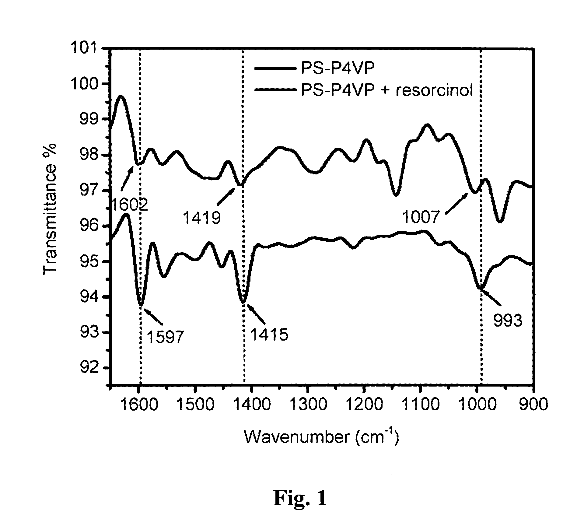
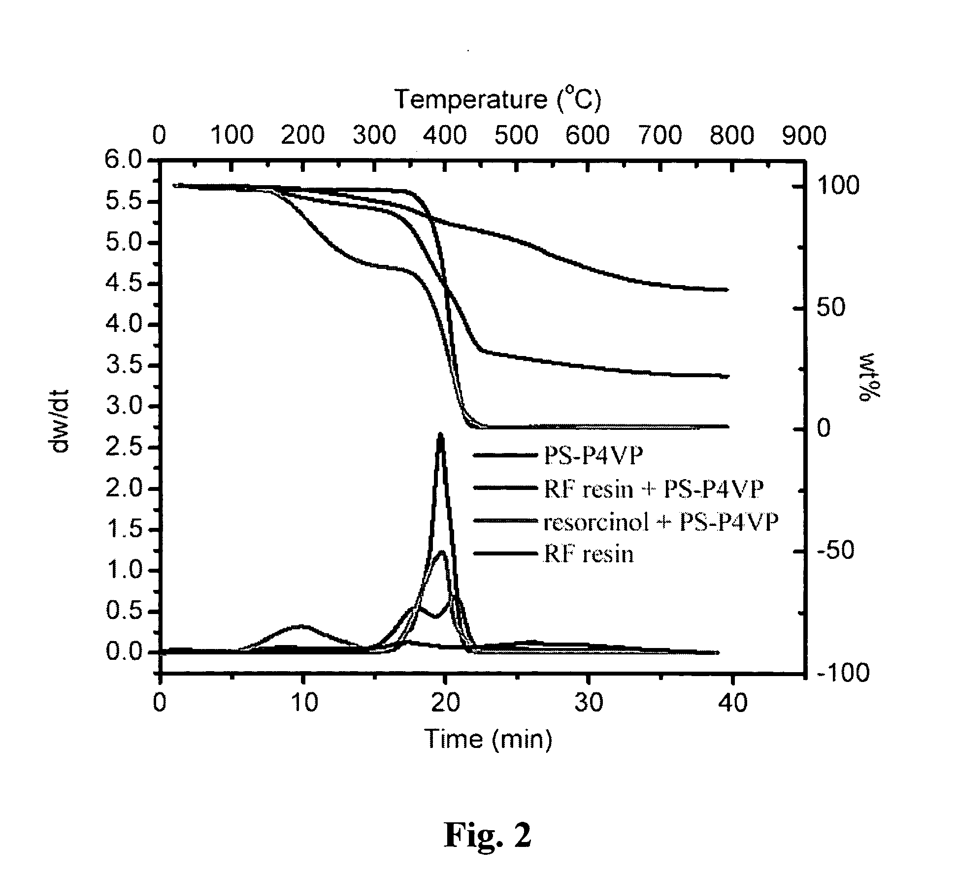
[0031] Spatial organization of the phenolic resin monomer by block copolymers: Phenolic resin is used as carbon precursors. First, 0.1 g poly(styrene-block-(4-vinylpyridine)) (PS-P4VP), with average molecular masses (Mn) of PS 11,800 g / mol, P4VP 11,500 g / mol and Mw / Mn=1.04 for both blocks, and 0.0512 g resorcinol were dissolved in 2 g of dimethylformalamide (DMF). (Mw is the weight average molecular weight of the polymer. This solution was heated at 100° C. for 4 hours to ensure the formation of hydrogen bond. After the solution was cooled to room temperature, a drop of solution was cast into a film on a silica plate by spin coating at 1000 rpm for 2 minutes. The film was subsequently dried in a hood. The dry film along with 2 small vials which contain DMF and benzene, respectively, was then put into a preheated chamber at 80° C. The film remained in the chamber for 24 hours to allow the completion of microphase separation. The microphase separated film was dried in air and sequenti...

example 2

[0032] Spatial organization of polymerization catalyst by block copolymers: Poly furfural alcohol was employed as carbon precursor. 0.1 g poly(ethyleneoxide-block-propyleneoxide-block-ethyleneoxide) (PEO-PPO-PEO) triblock copolymer and 0.01 g p-toluenesulfonic acid were dissolved in 2 g tetrahydrofuran (THF). A film was cast by using this solution by dip coating at 40° C. The cast film was then annealed in THF vapor in a 24 hour period. The annealed film was thoroughly dried under vacuum and then exposed to furfural alcohol gas for about 30 minutes at room temperature. A black poly(furfuryl alcohol) was formed on the film. This film was stabilized at 100° C. overnight to ensure the completion of polymerization. The film was carbonized in nitrogen gas through a temperature ramp of 1° C. / min to 800° C.

example 3

[0033] Spatial organization of linear polymer via the self assembly of block copolymers: Neither catalyst nor monomer was used in this route. Poly(4-hydroxyl-styrene) was used as carbon precursor after it had been cross-linked with formaldehyde. 0.1 to 20 wt % of poly(styrene-block-4-hydroxyl-styrene) in THF was cast to substrates. The structure of the film was refined in the THF vapor for 24 hours. The film was then thoroughly dried in a vacuum oven at 50° C. The dry film was cross-linked in formaldehyde gas at 80° C. for 10 hours before it had been finally carbonized through a temperature ramp of 1° C. / min to 800° C. The carbonized film had an ordered nanostructure dependent upon the ratio of the two blocks. In general, with PS block in the range of less than 20 percent, the resulted carbon film has a cubic porous structure; PS block in the range of 20-40% yields hexagonal cylindrical pores; PS block in the range of 40-60% yield lamellar carbon sheets; PS block in the range of 60-...


PUM

PropertyMeasurementUnit
pore sizesaaaaaaaaaa
thicknessaaaaaaaaaa
temperatureaaaaaaaaaa

Abstract

Applicant's present invention comprises a method for fabricating porous carbon materials having highly ordered nanostructures comprising the steps of first, forming a precursor solution comprising a block copolymer template and a carbon precursor; second, forming a self-assembled nanostructured material from the precursor solution; third annealing the nanostructured material thereby forming a highly ordered nanostructured material; fourth, polymerizing the carbon precursor to cure the nanostructured material; and pyrolyzing the nanostructured material wherein the block copolymer template is decomposed to generate ordered carbon nanopores and the nanostructured material is carbonized to form the walls of the carbon nanopores thereby forming a porous carbon material having a highly ordered nanostructure. In addition, the present invention further comprises a porous carbon material comprising a carbon nanostructure having ordered carbon nanopores that have uniform pore sizes ranging from about 4.5 nm up to about 100 nm.

Description

[0001] The United States government has rights in this invention pursuant to contract no. DE-AC05-00OR22725 between the United States Department of Energy and UT-Battelle, LLC.FIELD OF THE INVENTION [0002] The present invention relates to porous carbon materials and more particularly, to highly ordered porous carbon materials having well defined nanostructures. BACKGROUND OF THE INVENTION [0003] Elemental carbon materials exhibit unique electron, mechanical, and chemical properties that make them attractive materials for nanoelectronic devices, strength-enhancing materials, separation media, catalyst supports, energy storage / conversion systems (hydrogen storage, fuel cell electrodes, etc.), proximal probes, optical components, etc. Well-defined nanoporous carbon materials are essential for a number of the aforementioned applications. Although numerous methods have been developed for the fabrication of carbon films such as chemical vapor deposition, ultrasonic deposition, hydrotherma...

Claims


Application Information

Patent Timeline
Patent Type & Authority Applications(United States)
IPC IPC(8): C01B31/02
CPCC01B31/02C01B31/00C01B32/00C01B32/05
Inventor DAI, SHENGLIANG, CHENGDU
Owner UNIV OF TENNESSEE RES FOUND
Why Eureka
Try Eureka