Controllable Synthesis of Porous Carbon Spheres, and Electrochemical Applications Thereof

a porous carbon sphere and synthesis technology, applied in the field of porous carbon spherical morphology, can solve the problems of negative effects on other parameters, non-linear function of carbon surface area and porosity, energy crisis and environmental pollution, etc., and achieve the effects of high efficiency, superior orr activity, and high dispersion of metal nanoparticles

Inactive Publication Date: 2011-04-07
NAT RES COUNCIL OF CANADA
View PDF7 Cites 69 Cited by
  • Summary
  • Abstract
  • Description
  • Claims
  • Application Information

AI Technical Summary

Benefits of technology

[0033]According to further aspects of the invention, the porous carbon spheres according to the invention are used for example, as catalyst supports to prepare Pt and Pt alloy catalysts for oxygen reduction reaction (ORR) and methanol oxidation reaction (MOR) in PEM fuel cells, including direct methanol fuel cells. High dispersion of metal nanoparticles and superi...

Problems solved by technology
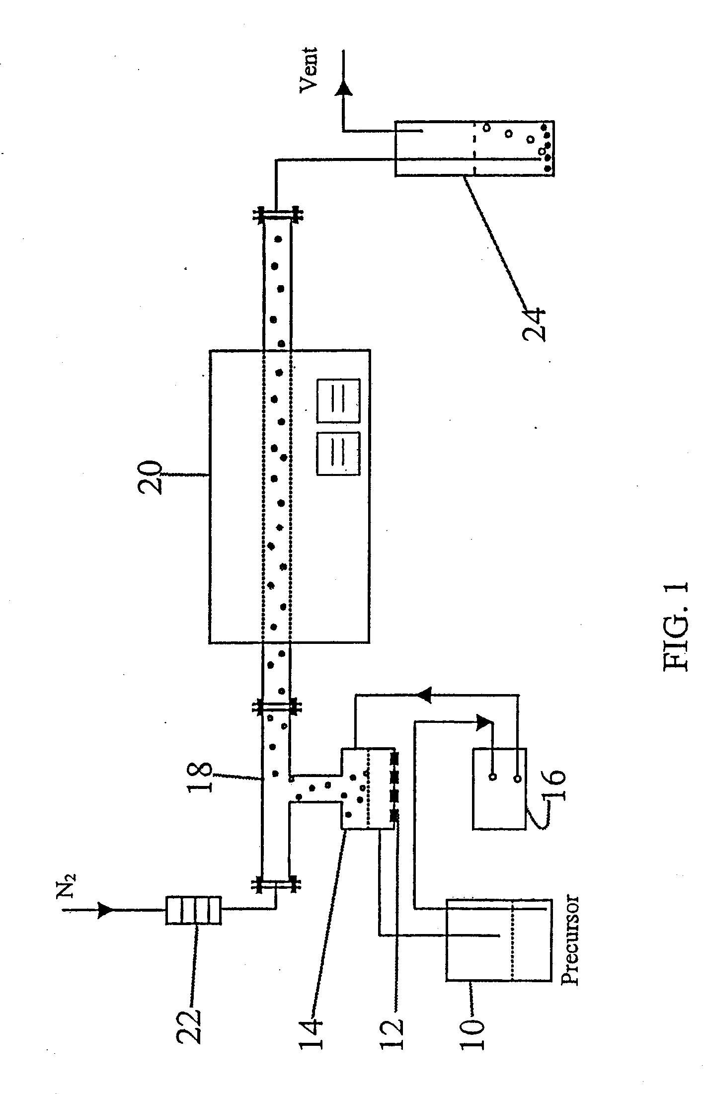
Nowadays, energy crisis and environment pollution are two serious challenges facing humans.
However, electrochemical performance is not a linear function of carbon surface area and porosity.
The increase of surface area and porosity may result in some negative effects on other parameters such as electronic conductivity, hydrophilicity, specific volume and density.
However, most the commercially available carbon blacks, which usually manufactured by pyrolyzing hydrocarbons such as natural gas or oil fractions taken from petroleum processing, cannot match such a requirement of controllably synthesizing carbon materials wi...

Method used


Image

  • Controllable Synthesis of Porous Carbon Spheres, and Electrochemical Applications Thereof
  • Controllable Synthesis of Porous Carbon Spheres, and Electrochemical Applications Thereof
  • Controllable Synthesis of Porous Carbon Spheres, and Electrochemical Applications Thereof

Examples


example 1

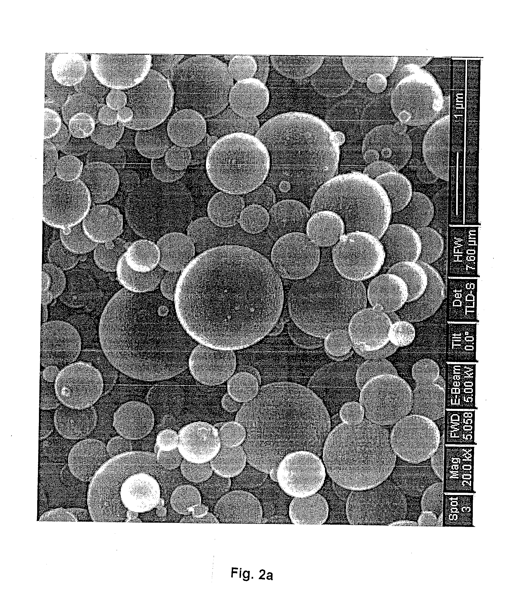
[0059]In this example, porous carbon spheres were synthesized by 22-nm colloidal silica templates, according to the detailed process described above. In this case, sucrose was used as carbon source, with the silica to carbon weight ratio of 2:1.

[0060]FIG. 2a shows the SEM picture of the carbon-silica composite particles synthesized by 22-nm colloidal silica templates. The composite particles have completely spherical shape and smooth surface.

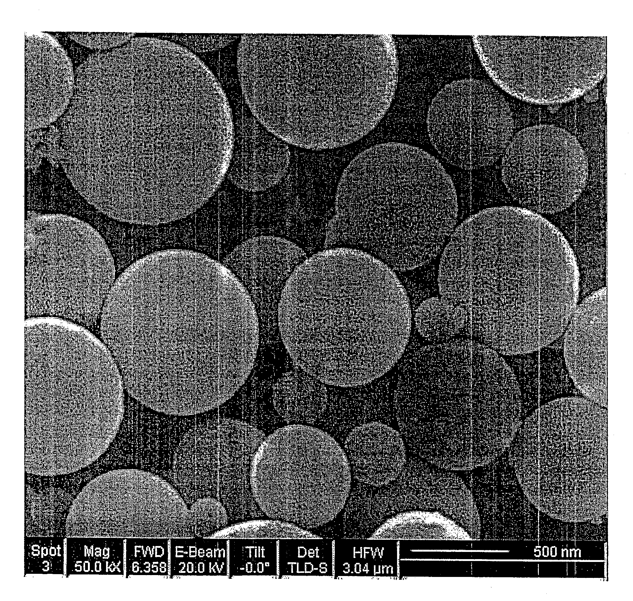
[0061]FIG. 2b shows the SEM picture of the carbon spheres after etching silica. FIG. 2c is a zoomed picture of a single carbon sphere. It is clear that the etching process doesn't destroy the spherical shape of the primary particles. The silica content was etched from the carbon matrix, which resulted in a honeycomb-like carbon sphere with many uniform nanosized pores. The TEM picture of a single carbon sphere (FIG. 2d) shows that the carbon sphere is hollow. The particle size of porous carbon sphere displays a unimodal distribution around 1000 ...

example 2

[0064]In order to improve the stability of such an open frame carbon structure, a graphitic carbon sphere structure was introduced by adding a catalytic graphitization step into the procedure described in example 1. A transition metal ion e.g. Fe, Co, Ni or others in the &qui of a salt (chloride, sulfate, nitrate, acetate etc.) was added into the precursor solution with a metal / carbon source weight ratio from 1:20 to 1:5. The metal or metal oxide nanoparticles derived from the decomposition of the salt acted as a catalyst in step (3) to graphitize the porous carbon sphere. FIG. 6 shows the XRD patterns of porous carbon sphere before and after graphitization. Obvious graphite peaks can be seen in the second sample. Besides the benefit of a more stable structure, the graphitic carbon sphere also has a higher electronic conductivity (10 S / cm) than the pre-graphitized carbon sphere (˜1 S / cm). The electronic conductivity was measured at room temperature by AC impedance spectroscopy over ...

example 3

[0065]One of the examples of applications / uses for the porous carbon according to the invention is mesoporous carbon sphere supported Pt and Pt alloy catalysts prepared by a co-formation procedure, for oxygen reduction reaction, particularly in proton exchange membrane fuel cells. For other applications, other noble metal alloy catalysts can be used e.g. Pt—Ru for methanol oxidation in DMFCs.

[0066]The step of adding the catalyst particles may be done either after the formation of the spherical porous carbon, or it can be done concurrently by co-formation. One process is co-formation procedure; another is conventional impregnation procedure (microwave-assisted polyol method).

[0067]A co-formation procedure, which was based on the above-described procedure, was used to synthesize porous carbon sphere supported Pt and Pt alloy. Pt salt or mixture of Pt and transition metal (Co, Ni, Fe, Mn etc.) salts were dissolved in the reaction precursor, which includes carbon source (sucrose, pyrrol...


PUM

PropertyMeasurementUnit
Temperatureaaaaaaaaaa
Pore size distributionaaaaaaaaaa

Abstract

The invention disclosed relates to porous carbon of spherical morphology having tuned porosity and to a method of making same, comprising: (a) providing a precursor solution, by combining in an aqueous solution a colloidal silica template material and a water-soluble pyrolyzable carbon source, wherein the particle size of the colloidal silica template and the colloidal silica/carbon source weight ratio are controlled, (b) atomizing the precursor solution into small droplets by ultrasonic spray pyrolysis (c) directing the droplets into a high temperature furnace operating at a temperature of 700-1200° C., under an inert gas atmosphere, where the droplets are transformed into solid spherical composite carbon/silica particles, (d) collecting the resulting composite carbon/silica particles exiting from the furnace, and (e) removing the silica from the particles, to provide substantially pure porous carbon of spherical morphology having tuned porosity defined by surface area and pore size. The porous carbon according to the invention is used as catalyst supports in PEM fuel cells, as electrodes in supercapacitors and lithium in batteries, for hydrogen storage and as earners for drug delivering.

Description

BACKGROUND OF THE INVENTION[0001]This invention relates to porous carbon of spherical morphology, having tuned porosity as defined by surface area and pore size, and to a method of making same.[0002]Nowadays, energy crisis and environment pollution are two serious challenges facing humans. People throughout the world show more and more concerns of developing sustainable and environmentally friendly energy sources and energy devices to replace the current petroleum- and ICE—(internal combustion engine) based energy systems. Electrochemical energy conversion and storage devices including fuel cells, batteries and capacitors are the most promising approaches to address the global energy and environment issue.[0003]In these electrochemical systems, carbon material is a key component to assist successful conversion of chemical energy directly to electric energy. For example, in proton electrolyte membrane fuel cells, porous carbon is used as catalyst support to improve the dispersion and...

Claims


Application Information

Patent Timeline
IPC IPC(8): B01J21/18C01B31/02B01J37/34B32B5/16B01J35/00B82Y40/00
CPCA61K9/51Y10T428/2982B01J20/20B01J20/28019B01J20/28057B01J20/28078B82Y30/00C01B3/0021C01B31/00H01G11/42H01M4/587H01M4/926H01M8/04216H01M10/0525Y02E60/13Y02E60/325Y02E60/50H01G11/24A61K47/02C01B32/00Y02E60/10Y02E60/32Y02P70/50
Inventor LIU, HANSANZHANG, JIUJUN
Owner NAT RES COUNCIL OF CANADA
Why Eureka
Try Eureka