Fuel cell electrode

Inactive Publication Date: 2006-05-11
NEWCASTLE UNIV VENTURES
View PDF13 Cites 33 Cited by
  • Summary
  • Abstract
  • Description
  • Claims
  • Application Information

AI Technical Summary

Benefits of technology

[0072] The mesh supported electrocatalysts of fuel cells of the present invention provide enhanced anode over-potential performance and facilitate improved gas evolution from the surface of the electrode during the oxidation of liquid fuels. This brings about improvements in fuel cell performance.
[0073] Additional benefits derived from the present invention include higher power densities and a more flexible operation resulting from the greater range of fuel concentrations that are accessible. Furthermore, the present invention provides a relatively simple electrode structure which can be fabricated using known expertise in the manu

Problems solved by technology

Conventional electrode structures suffer from poor diffusion of reaction products away from the electrode surface, and this makes it difficult for fuel to reach the electrode surface.
Put simply, the products or by-products of the electrochemical reaction at the electrode surface are not efficiently removed and therefore hinder the influx of fuel.
This problem is particularly acute where the product is a gas because a build up of gas on the electrode surface presents a significant barrier to the influx of liquid fuel.
In particular the formation of CO2 gas at the anode in known hydrocarbon based fluid fuel cells, such as a DMFC, blocks access of the hydrocarbon based fuel to the anode surface which reduces the effectiveness

Method used


Image

  • Fuel cell electrode
  • Fuel cell electrode
  • Fuel cell electrode

Examples


example 1

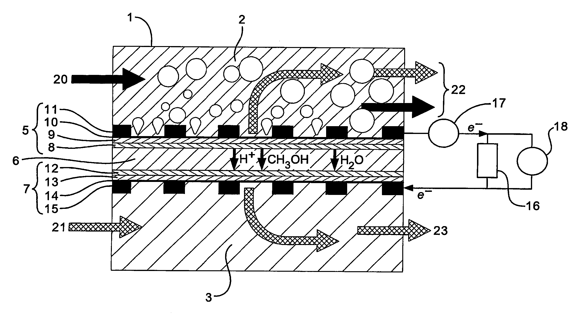
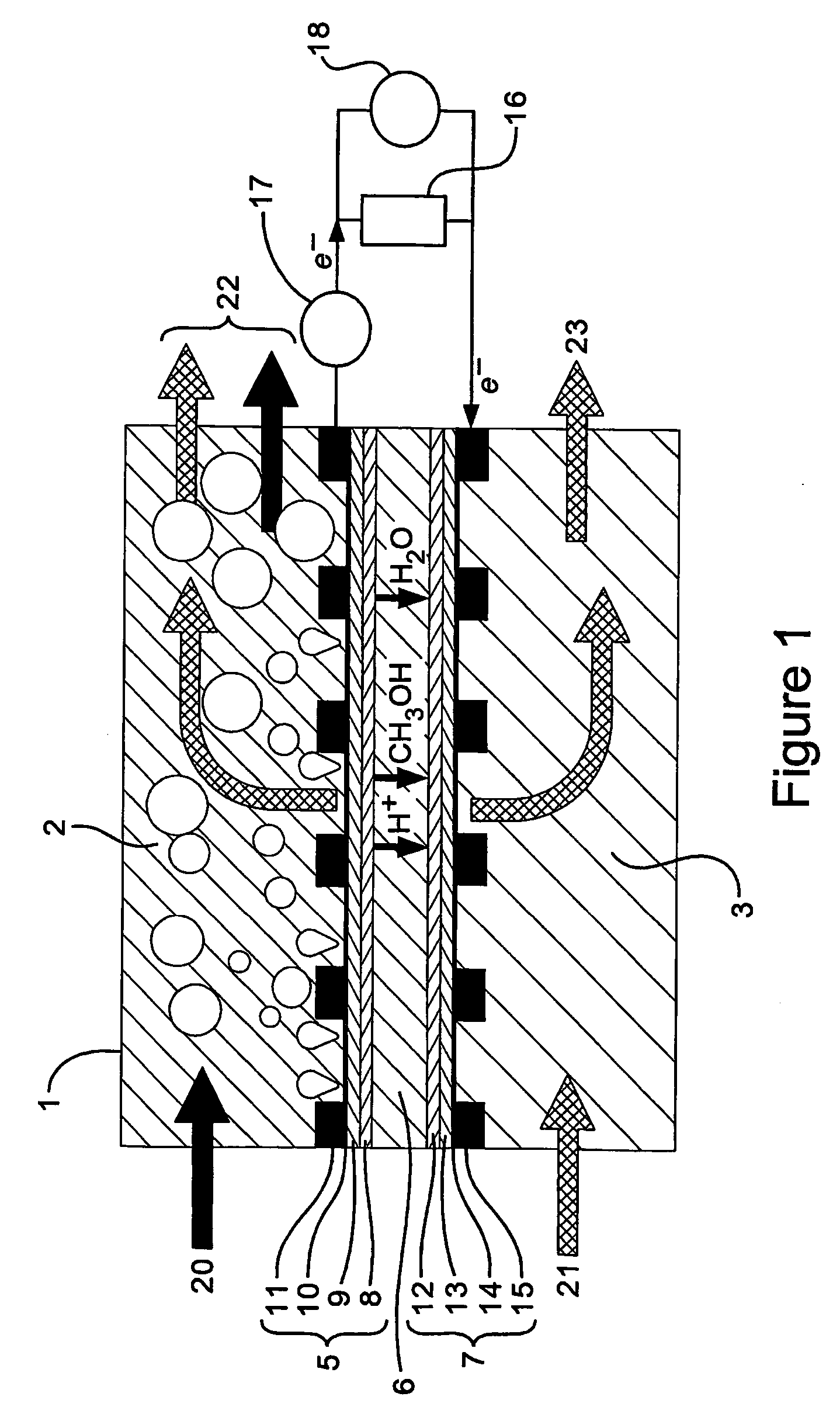
Operation of Membrane Electrode Assembly

[0108] The following MEAs were prepared:

MEAAnodeFormed byCathodeFormed by1PtRu Ti mesh 3ThermalPtChemical(1:1 1.5 mgcm−2)deposition(0.4 mgcm−2)deposition2PtRu Ti mesh 3ThermalPt on ADPChemical(1:1 1.5 mgcm−2)depositionmembranedeposition(1.1 mgcm−2)3PtRu Ti mesh 3ThermalPtChemical(1:1 1.5 mgcm−2)deposition(0.4 mgcm−2)deposition4PtChemicalPtChemical(0.645 mgcm−2)deposition(0.7 mgcm−2)deposition5PtRu Ti mesh 3ThermalPtChemical(1:1 1.5 mgcm−2)deposition(0.4 mgcm−2)deposition6PtRu Ti mesh 3ThermalPtChemical(1:1 1.5 mgcm−2)deposition(1.1 mgcm−2)deposition

[0109] The MEAs were conditioned for 48 hrs in a test fuel cell at 75° C. and atmospheric pressure with a continuous feed of 2 M methanol. The MEAs were then tested in an alkaline fuel cell at different conditions to ascertain reproducibility of their performance.

[0110] The alkaline fuel cell uses methanol as a fuel in an alkaline sodium hydroxide solution. The structure of the fuel cell is as d...

example 2

Effect of Mesh Structure on Performance

[0121] Three mesh electrodes having a rhombus pore shape and each having a different pore size and strand width were prepared using the thermal decomposition method described above and are shown in FIG. 6. The Ti mesh electrodes were coated with PtRu (Pt:Ru=0.5:0.5 in atomic ratio). The geometric parameters of the three mesh electrodes are listed as in Table 1, and SEM images of the meshes are shown in FIG. 6. The pore size dimensions LWD and SWD are illustrated in FIG. 6 and correspond to the long and short dimensions of the rhombus pores.

TABLE 1ParametersMesh 1Mesh 2Mesh 3Pore sizeLWD / mm1.2810.52SWD / mm0.720.640.36Strand width / mm0.140.180.08

[0122]FIG. 7 shows the galvanostatic performance of the different electrodes in 2 M MeOH+0.5 M H2SO4 at 60° C. The galvanstatic performance of an electrode is a measure of the steady state current density as a function of electrode potential. The PtRu catalyst thermally deposited on Ti mesh 3 possesses t...

example 3

Comparison of Conventional Fuel Cell with Ti Mesh Fuel Cell

[0123] A fuel cell according to the present invention comprising an electrocatalyst coated Ti mesh was compared with a conventional fuel cell comprising a carbon cloth electrode gas diffusion electrode.

[0124]FIG. 8 shows two cell voltage versus current density curves obtained from a flow DMFC operating with two anode structures: a Pt—Ru / Ti mesh anode according to the present invention made by thermal deposition, and a conventional Teflon bonded carbon cloth gas diffusion anode. Each has a catalyst loading of 2 mg Pt+1 mg Ru cm−2. The cathode was a conventional carbon cloth arrangement in both cells. FIG. 8 was obtained by flowing a 2 M methanol solution at 90° C. to the anodic chamber and by passing 1.5 bar air into the cathodic chamber, and recording the cell performance with each of the anode structures.

[0125] The anode structure according to the present invention comprises a membrane electrode assembly comprising a PtR...


PUM


Abstract

A fuel cell (1) having an electrode comprising an electrocatalyst (32) on a support, wherein the support is a mesh (30) of conductive material such as a metal, metal alloy and metal composite (e.g. titanium or titanium alloy), is disclosed, as well as a method of operating such a fuel cell by contacting a fuel and an oxidant on said electrode. The electrolyte of the fuel cell may be an ion exchange membrane.

Description

FIELD OF THE INVENTION [0001] The invention relates to fuel cells and in particular to electrodes for use in fuel cells. BACKGROUND TO THE INVENTION [0002] Fuel cells convert the chemical energy of a fuel into electrical energy. A fuel cell comprises an anode, a cathode and an electrolyte separating the anode and cathode. A fuel cell has an inlet or anode compartment for delivering fuel to the anode and an inlet or cathode compartment for delivering oxidant to the cathode. The simplest fuel cell is one in which hydrogen is oxidised to form water over, for example, nickel electrodes. Oxygen gas is delivered to the cathode where it is reduced to produce hydroxide ions, and hydrogen is delivered to the anode where it is oxidised to produce water. The nickel acts as a catalyst. Electrons flow through an external circuit connecting the anode and cathode, thereby generating an electric current. [0003] Fuel cells have a number of advantages over other power generating technologies, for exa...

Claims


Application Information

Patent Timeline
IPC IPC(8): H01M8/00H01M4/86H01M4/88H01M4/90H01M4/92H01M8/02H01M8/04H01M8/10
CPCH01M4/8605H01M4/921H01M8/0232H01M8/04089H01M8/1011Y02E60/523Y02E60/50H01M4/86H01M8/02
Inventor SCOTT, KEITHCHENG, HUA
Owner NEWCASTLE UNIV VENTURES
Why Eureka
Try Eureka