Optical component and method of manufacture of optical component

a technology of optical components and optical components, applied in the field of optical components, can solve the problems of unsuitable mass production of components, affecting the compactness of optical systems, and high cost of quartz raw materials, and achieves the effect of high degree of freedom of design and easy manufacturing

Inactive Publication Date: 2006-06-08
OHARA
View PDF20 Cites 5 Cited by
  • Summary
  • Abstract
  • Description
  • Claims
  • Application Information

AI Technical Summary

Benefits of technology

[0024] An object of this invention is to provide an optical component or optical low-pass filter which can be easily manufactured, and which, from the standpoint of material selection, structure or similar, enables a high degree of freedom of design.

Problems solved by technology

An optical low-pass filter which employs the birefringence of quartz incurs the expensive raw material costs of the quartz, and in particular requires a plurality of sheets of quartz and becomes thick when contemplating use in a color video camera using a solid-state image capture element, so that there are limits placed on the compactness of the optical system.
Moreover, problems of precise optical axis alignment, and of strain when bonding sheets together, as well as numerous other problems related to manufacture make such components unsuitable for mass production.
On the other hand, conventional optical low-pass filters employing phase-type diffraction gratings, obtained by fabrication the surface of a material, have the following problems from the standpoint of device manufacture.
For example, when using lithography, there are numerous processes as explained above, and the time required leads to increased fabrication costs.
On the other hand, when an attempt is made to for example fabricate a rectangular-shape grating with large step height differences, in consideration of the ease of fabrication, it is not easy to machine grooves which are deep in the vertical direction.
Further, it may be necessary to select optimal environment conditions for dry etching depending on the material, and in other respects also control is complicating, and there is little degree of freedom in choice of materials.
In addition, due to the nature of the fabrication method, fabrication of the surface is limited to two dimensions, so that there is little degree of freedom in the design of the structure.
However, limitations are imposed on the selection of materials.
That is, in the case of a hot-pressed replica, the material for fabrication is limited to glass and resin.
Further, in the case of a hot-pressed replica, when choosing the mold and material for fabrication, the durability of the mold with respect to the softening temperature of the glass is an issue; and conversely, the material should be preferably selected with this born in mind.
When cutting using a diamond wheel, mass production properties are poor compared with molding of glass or resin using a mold, and there are problems with fabrication multiple-angled or curving filter patterns.
Accordingly, there is little degree of freedom in choosing shapes at the design stage, and shape precision is poor.
Moreover, the mechanical strength of the material becomes an issue, so that there is little degree of freedom in choice of material as well.
Methods in which ion exchange techniques or similar are used to form portions on a glass surface the refractive index of which differs are in essence material surface fabrication methods, and so there is little degree of freedom of pattern design.
This is performed by immersion in a fused-salt reactor, and the processes involved are complex.

Method used


Image

  • Optical component and method of manufacture of optical component
  • Optical component and method of manufacture of optical component
  • Optical component and method of manufacture of optical component

Examples


first embodiment

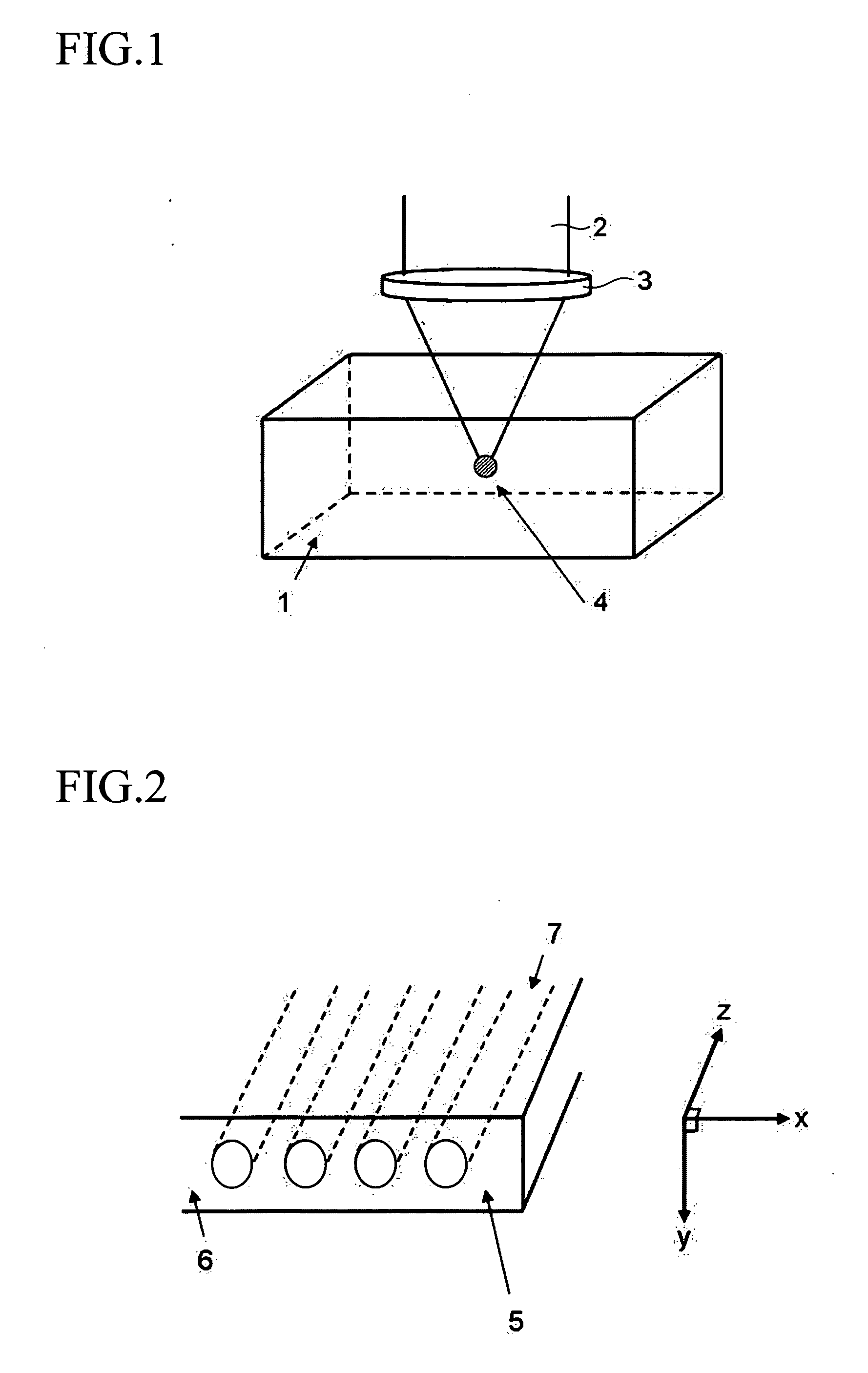
[0129] As an optical filter, FIG. 2 shows an optical low-pass filter 5. Here, in this structure regions7 of refractive index N(x, y) different from the refractive index n0 of the substrate are formed in the interior 6 of the transparent substrate with refractive index n0, formed using the method of FIG. 1, in stripe shapes having width a and interval p with periodicity only in the x direction in which the component is to act as the optical low-pass filter. The component this acts as an optical low-pass filter with respect to an object having a high spatial frequency component in one direction.

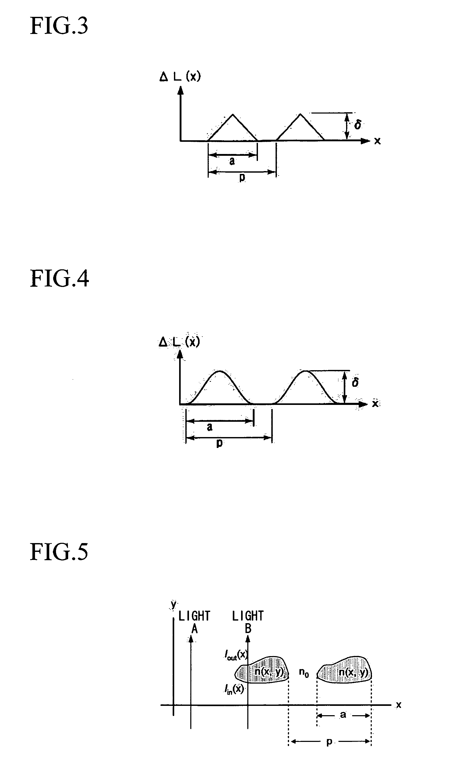
[0130] In this embodiment, if the cross-sectional shape of the region 7 in the x-y plane of the optical low-pass filter 5 is y=l(x), then the difference ΔL(x) in the optical distances traveled by the light A traversing only the substrate with refractive index n0, and the light B traversing the coordinate x, is expressed by the following equation (1). Δ⁢ ⁢L⁡(x)=∫lin⁡(x)lout⁡(x)⁢N⁡(x,y)⁢ ⁢ⅆy-n0⁢...

embodiment 1

[0136] In the above embodiment, regions 7 with refractive index N(x, y) are formed within a substrate with refractive index n0 in stripe shapes, having periodicity in the x direction in the interior of the transparent substrate 6; but an optical low-pass filter of this invention is not limited to the above embodiment, and the periodic structure of a heterogeneous phase in the embodiment 1 may be formed at a different depth in the same substrate, so as to have a periodicity in a different direction.

second embodiment

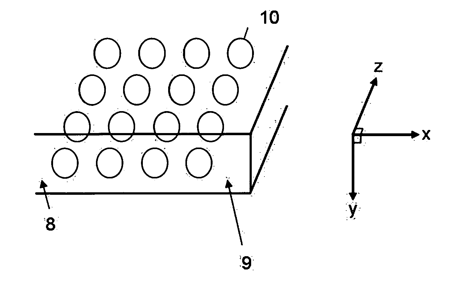
[0137] Moreover, an optical low-pass filter 9 can be realized in which the region 10 with refractive index N(x, y, z) is formed and arranged in two dimensions to act in two or more directions, having periodicity in the interior of the substrate 8 with refractive index no, such that the refractive index N(x, y, z) or the shape l(x, y, z) also changes in the z direction in FIG. 2. FIG. 12 shows such an optical low-pass filter of a

[0138] The optical low-pass filter 9 of the second embodiment is such that the regions 10 with refractive index N(x, y, z) has periodicity in the x direction and in the z direction, and so has an optical distance difference ΔL(x, z) characteristic as indicated by equation (3) below, and acts as an optical low-pass filter in two or more directions of the object image. Δ⁢ ⁢L⁡(x)=∫lin⁡(x)lout⁡(x)⁢N⁡(x,y,z)⁢ ⁢ⅆy-n0⁢l⁡(x,z)(3)

[0139] In this embodiment, as a low-pass filter for a CCD having a pixel arrangement in which pixels are arranged with width 3 μm at interv...


PUM

PropertyMeasurementUnit
wavelengthsaaaaaaaaaa
refractive indexaaaaaaaaaa
wavelengthaaaaaaaaaa

Abstract

An optical component or optical low-pass filter has two or more regions demarcated by differences in refractive indexes, in which a region having a refractive index different from the refractive index of the continuous region with the largest volume among the two or more regions is formed in the interior of a transparent material. This optical component or optical low-pass filter has regions with different refractive indexes formed in the interior by pulsed laser irradiation or focused irradiation of the transparent material.

Description

BACKGROUND OF THE INVENTION [0001] Priority is claimed on Japanese Patent Application No. 2004-351632, filed Dec. 3, 2004, the content of which is incorporated herein by reference. [0002] 1. Field of the Invention [0003] This invention relates to an optical component manufactured using pulsed laser beam, and in particular pulsed laser beam the time duration of which is 10−12 second or less, such as femtosecond (10−15 second) pulses, and in particular relates to an optical low-pass filter suitable for solid-state image capture elements such as are used in video cameras, digital still cameras, fiberscopes and similar, as well as a manufacturing method for same. Such components are also suitable for use as optical low-pass filters in liquid crystal, plasma, EL, SED and other displays, and other dot-matrix display devices. [0004] 2. Description of Related Art [0005] The spread of digital video cameras and digital still cameras in recent years has been accompanied by progress toward grea...

Claims


Application Information

Patent Timeline
Patent Type & Authority Applications(United States)
IPC IPC(8): G02B3/00
CPCC03C23/0025G02B27/56
Inventor HASHIMOTO, TOMOHIRO
Owner OHARA
Why Eureka
Try Eureka