[0018] The present invention provides a photoacoustic
system and method which can use a wide variety of
continuous wave (CW) lasers including inexpensive telecom
diode lasers. It provides a small, optically based sensor that is capable of detecting trace contaminants such as
water vapor at the level of a few ppbv in both
inert and corrosive process gases. In-line or at-line monitors according to the present invention will enable
wafer fabs to establish correlations between
moisture and / or other contaminant gas content and device quality. Precise knowledge of the relationship between contaminant content and device quality will accelerate yield improvement when fabs are introducing new processes. Given the short
product lifetime of today's integrated circuits, it is economically vital to bring new circuits to market as soon as possible. When leaks occur in the gas
distribution system, moisture monitors in accordance with the present invention will help
wafer fab engineers identify the
exact location and severity of the leaks sooner and more easily and thereby
cut the associated equipment
downtime from hours or even days to minutes. In-line or at-line monitors will help engineers identify the
root cause of a yield hit sooner, either by revealing a moisture or other contaminant problem or by enabling them to rule out e.g., moisture as the offender. Furthermore, monitors in accordance with the present invention will enable
wafer fabs to optimize the frequency of process tool maintenance by using moisture readings to indicate if maintenance is due. By optimizing the frequency of maintenance, wafer fabs will minimize costs associated with test wafers and other
consumables. The present invention will also enable wafer fab engineers to measure moisture in process tools after
preventive maintenance. After routine
preventive maintenance of tools such as a CVD chamber engineers normally purge the chamber to remove moisture. However, they typically have no objective measure of when the moisture content has been reduced sufficiently to stop the purge and resume fabrication processes. The monitors of the present invention will enable them to ensure safe moisture levels and to return the tool to productivity as soon as possible.
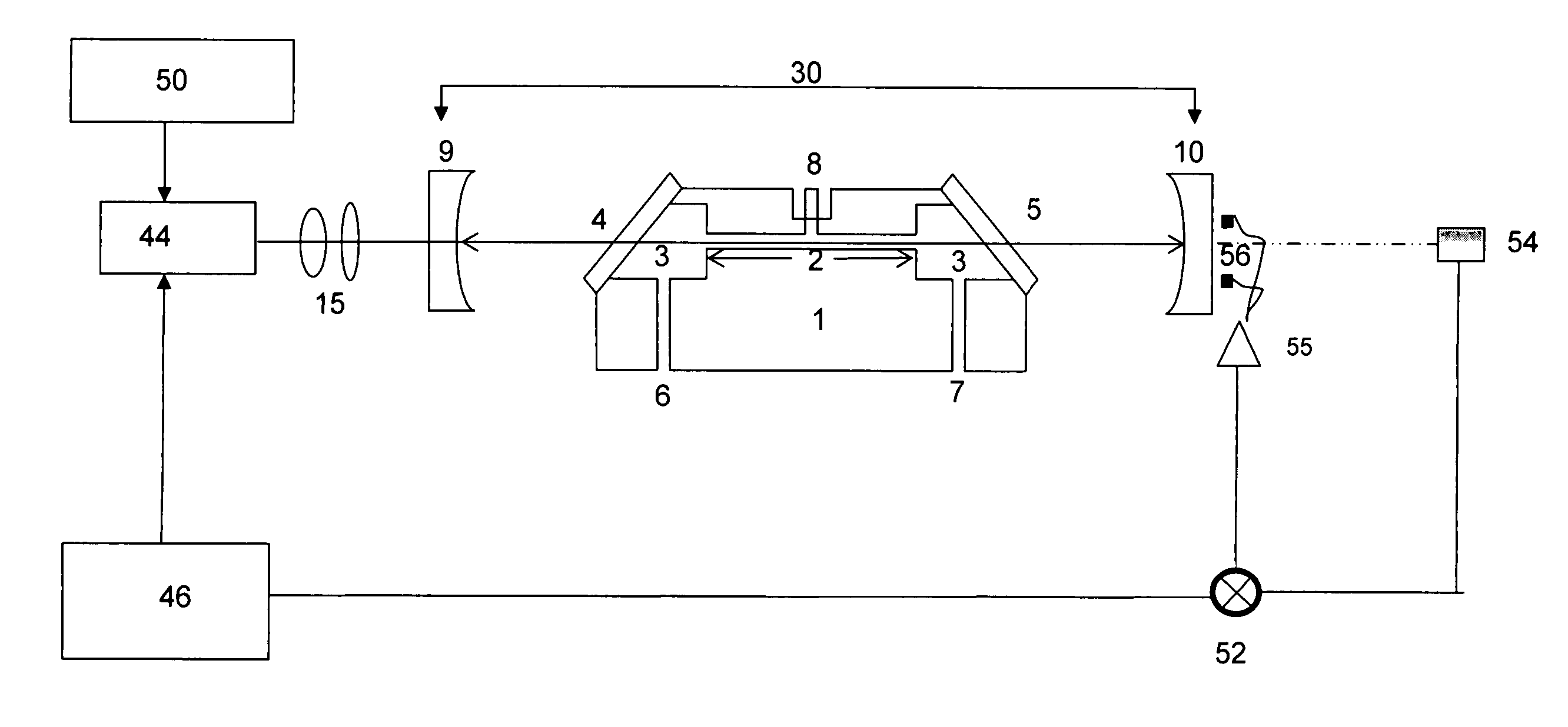
[0020] A unique aspect of the present invention is that it provides a resonant
optical cavity which enhances the
optical power used to excite the target
analyte contained within a
photoacoustic cell. The resonant optical cavity comprises at least two reflecting surfaces. The simplest configuration is a linear cavity with two mirrors (reflecting surfaces). However, the cavity can be composed of any number of mirrors that create a
closed path resonant optical cavity. A stable optical cavity can suitably utilize either flat or concave mirrors, or a combination thereof. For simplicity of fabrication, the mirrors will preferably have the same
reflectivity and
radius of curvature. As an alternative, one of the reflecting surfaces can be a crossed
polarizer. At least one optical element in the
system will be translatable so as to change the phase of the electromagnetic wave and enable the optical cavity and the modulated
laser source to track one another, so that light builds up inside the optical cavity.
[0026] The locking
system can either move one of the cavity mirrors, as is typically used in electronic tracking (locking), or move the cavity input mirror as is typically used in optical locking. The most well-known electronic locking technique is Pound Drever Hall [see for example Ye, J, Ma, L S, Hall, J L, J. Opt. Soc. Am. B, 15, 6 (1998) or Spence T G, Harb C C, Paldus B A, Zare R N, Willke B, Byer R L., Rev. Sci. Instrum., 71, 347 (2000)], where the frequency sidebands generate an
error signal to feedback to the
laser wavelength or cavity length. Other electronic locking methods include [Fox, R W, Oates, C W, Hollberg, L W, “Stabilizing
diode lasers to high
finesse cavities”, in Cavity-Enhanced Spectroscopies, eds. Van Zee, R D, Looney, J P,
Experimental Methods in the Physical Sciences, Vol. 40, Elsevier Science, New York (2002)] a “periodic” locking combined by
diode laser current switching, and tracking by dithering the laser current or cavity length [Romanini D, Kachanov A A, Sadeghi N, Stoeckel F, Chem. Phys. Lett., 264, 316 (1997) and Romanini, A. A. Kachanov, and F. Stoeckel, Chem. Phys. Lett., 270, 538 (1997)]. Electronic locking has been demonstrated for both linear and ring optical cavities. Optical locking has been demonstrated using
fixed length V-cavities and dithering the position of the input mirror. “Optical” locking of a DFB laser to a single cavity mode produces a strong effect, which narrows the laser
emission spectrum (to match the cavity mode linewidth) and significantly enhances both light injection and transmission through the cavity. Detailed descriptions of both the
physics and the detailed implementations of this locking scheme have been reported [Morville, J, Chenevier, M, Kachanov, AA, Romanini, D, SPIE Proc., 4485, 236 (2002) and Morville, J, Romanini, D, Chenevier, M, Kachanov, AA, Appl. Opt., 41, 6980 (2002) and Morville, J, Romanini, D, Kachanov, AA, Chenevier, M, Appl. Phys. B, 78, 465 (2004)].

