Separator for fuel cell and fuel cell using it

a fuel cell and separator technology, applied in the direction of cell components, cell component details, electrochemical generators, etc., can solve the problems of insufficient contact area with the electrode, difficult to provide the desired power-generating performance, and difficulty in forming a channel having a desired depth and a desired width, etc., to achieve the effect of reducing cost, reducing cost, and prolonging li

Inactive Publication Date: 2006-07-06
HITACHI LTD
View PDF3 Cites 28 Cited by
  • Summary
  • Abstract
  • Description
  • Claims
  • Application Information

AI Technical Summary

Benefits of technology

[0027] In one embodiment of the present invention, a separator having a longer life can be provided at a lower cost by combination of a flat plate-shaped metallic plate provided with a corrosion-preventing coating layer and electrically conductive channel plate. One separator can be formed by clamping a flat plate-shaped coated metal plate between two channel plates having a plurality of punched zigzag or straight channels for permitting the flowing of the reaction gas. One of the two electrically conductive channel plates is disposed so that a portion of each of the through-channels is overlapped with each of the manifolds in the electrically conductive flat plate, and the through-channels in the other electrically conductive channel plate exists as far as outside the coated metal plate. All of the separator having this structure can be formed by a punching process and hence, it is possible to reduce the cost and to ensure a sufficient contact area. Various tests regarding the life of the separator have been carried out and as a result, it has been made clear that the metallic portion corroded is observed remarkably at a portion through which electric current is passed. For this reason, in the present embodiment, the coating layer for suppressing the corrosion or the like is provided on the surface of the electrically conductive flat plate which is a metallic substrate. This means makes it possible to substantially extend the life of the separator.
[0028] By the fact that the through-channels in one of the channel plates are partially larger than the coated metallic plate, a rugged portion is formed, and serves as a fin, when a cell is produced by laminating the separator onto another member such as an electrolyte membrane. An outlet and an inlet are formed on adjoining faces of recesses and projections and hence, the reaction fluid is passed through the rugged fin. A cooling effect and the simplification of the cell structure are realized by the fact that the heat-transferring area is increased and the reaction fluid itself is a cooling medium.

Problems solved by technology

In a case of a separator having channels and formed by pressing of a thin metal plate, the processability or workability is restricted to a limit of the processability of a metal material and for this reason, it is difficult to form a channel having a desired depth and a desired width by processing.
This causes evil influences that the uniformity of the flowing of the reaction gas is not obtained and that a sufficient area of contact with the electrode cannot be provided, and as a result, it is difficult to provide a desired power-generating performance.
Even if the formation of a desired groove by processing is possible, a warpage or a strain may be generated in the separator produced after the processing, and a required finishing accuracy may be not provided in some cases, thereby bringing about the leakage of the reaction gas and an increase in contact resistance.
Another drawback of the separator formed by the pressing of the metal is a problem that each of apexes produced after the formation of the grooves has a curvature, and in a case of an integrated MEA comprising a gas diffusion layer and MEA formed integrally with each other, an area of contact with the integrated MEA is smaller and as a result, the resistance is increased, and a good power-generation performance cannot be obtained.
As a result, the following problem is arisen: The number of parts for constituting the cell is increased, and these parts are bound together by a conductive material, resulting in an increase in number of manufacturing steps.
As a result, the deterioration of the fuel cell might occur due to an increase in contact resistance, the pollution of the electrodes and the electrolyte membrane by a corrosion product and the like.
In addition, no attention is especially paid to the cooling of the body of the fuel cell in all of the above-described patent documents.

Method used


Image

  • Separator for fuel cell and fuel cell using it
  • Separator for fuel cell and fuel cell using it
  • Separator for fuel cell and fuel cell using it

Examples


embodiment 1

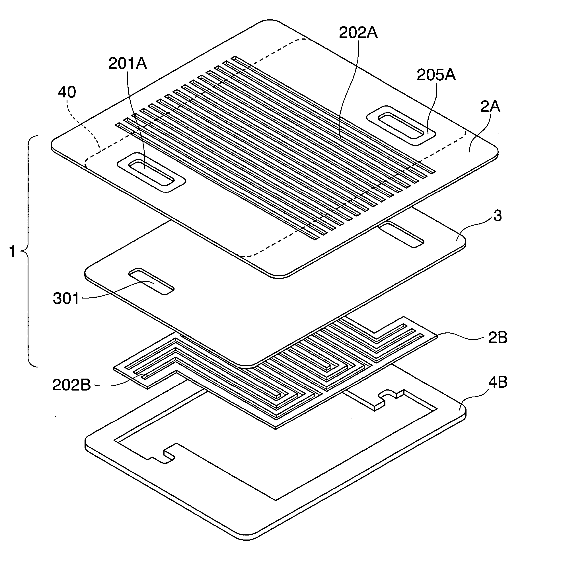
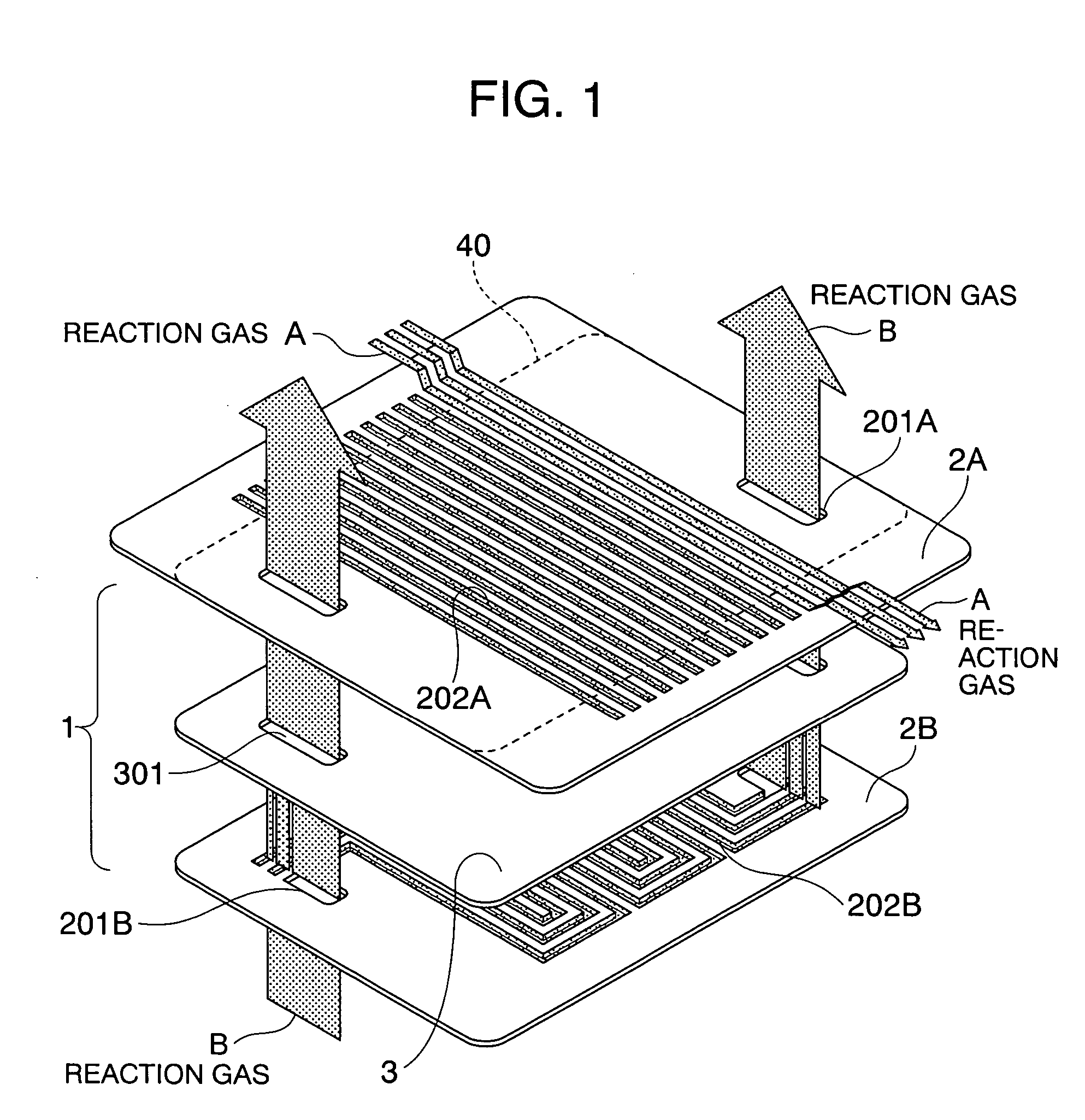
[0051]FIG. 1 shows the basic arrangement of a separator according to the present invention. The separator 1 in the present embodiment is comprised of a coated metal plate 3 and electrically conductive channel plates 2A and 2B. The coated metal plate 3 is formed by forming a corrosion-preventing coating layer on a flat plate-shaped metallic substrate. A plurality of manifolds 301 for passing a reaction fluid to an adjacent cell are formed in the coated metal plate. A plurality of serpentined through-channels 202B are provided in the channel plate 2B, and a plurality of manifolds 201B, as required, are formed in the channel plate 2B. A plurality of straight through-channels 202A are provided in the other channel plate 2A, and a plurality of manifolds 201A, as required, are formed in the channel plate 2A. The sizes of the coated metallic plate 3 and the channel plate 2B are equal or substantially equal to each other, but the size of the channel plate 2A is larger than those of the coat...

embodiment 2

[0062] An example in which each of channel plates 2A and 2B is a porous member will be described below with reference to FIG. 5. If each of the channel plates 2A and 2B is the porous member, the amount of gas supplied to the electrode through the channel plates is increased and hence, there is an effect of increasing a generated voltage and a diffusion-limited current. FIG. 5 is a view showing a separator 1 made using channel plates 2A and 2B which are porous members. Because the channel plates 2A and 2B are the porous members, a reaction gas is freely movable in the porous member. For this reason, a single channel plate 2 as described in Embodiment 1 cannot be used.

[0063] In this embodiment, a gasket 4B is disposed around the channel plate 2B, and sealing portions 205A are provided around the manifolds 201A in the channel plate 2A. Thus, it is possible to suppress the cross leakage of the reaction gas from an anode to a cathode and from the cathode to the anode, the leakage of the...

embodiment 3

[0066] An example including a coated metallic plate 3 provided with slits will be described with reference to FIGS. 7 to 9. FIG. 7 shows a separator 1 including the coated metallic plate 3 provided with the slits. The basic structure of the separator is the same as that described in Embodiment 1, except that the coated metallic plate is different. The positions of the slits 310 provided in the coated metallic plate 3 are determined so that through-channels 202A and 202B in a surface corresponding to an electrode are overlapped with each other upon superposition of a channel plate 2A and a channel plate 2B on each other. Such a situation is shown inFIG. 8.

[0067] A diagram of the two channel plates 2A and 2B superposed on each other is shown at a right and upper portion of FIG. 8, and a diagram of the coated metallic plate 3 provided with the slits 310 is shown at a left and lower portion of FIG. 8. FIG. 8 is a figure for convenience of the description, and the actual positional rela...


PUM

PropertyMeasurementUnit
areaaaaaaaaaaa
depthaaaaaaaaaa
depthaaaaaaaaaa

Abstract

The present invention can achieve the prevention of the corrosion of a metal separator, a reduction in contact resistance and an enhancement in cooling effect in a fuel cell. The separator includes an electrically conductive flat plate and two electrically conductive channel plates superposed on each other with the electrically conductive flat plate interposed therebetween. A plurality of manifolds for passing a reaction fluid to an adjacent cell are provided in the electrically conductive flat plate. A plurality of zigzag or straight through-channels for permitting the flowing of the reaction fluid from the manifolds are formed in each of the two channel plates. The through-channels in any one of the two electrically conductive channel plates are disposed so that they are partially overlapped with the manifolds in the electrically conductive flat plate, and the through-channels in the other electrically conductive channel plate are formed to be partially larger than the contour of the electrically conductive flat plate.

Description

BACKGROUND OF THE INVENTION [0001] 1. Field of the Invention [0002] The present invention relates to a separator, i.e. a Bipolar Plate separator, which is a member of a fuel cell, and a fuel cell using it. [0003] 2. Related Art [0004] There are several types of fuel cells, depending on the type of an electrolyte. A phosphoric acid-type fuel cell is of a type using phosphoric acid infiltrated in a support, and is operated at 150 to 220° C. A molten carbonate-type fuel cell is made using a mixture of lithium carbonate and potassium carbonate molded in an electrolyte support, and is operated at 600 to 700° C. A solid oxide-type fuel cell uses stabilized zirconia having an oxygen ion-conducting property as an electrolyte, and is operated at 700 to 1,000° C. In both of the fuel cells, hydrogen, a reformed gas, hydrocarbons or the like is used as fuel, and air is used as an oxidizing gas. [0005] Among various fuel cells, a polymer electrolyte fuel cell (PEFC) and a direct methanol-type fu...

Claims


Application Information

Patent Timeline
Patent Type & Authority Applications(United States)
IPC IPC(8): H01M8/02H01M2/08H01M4/94
CPCH01M8/0208H01M8/021H01M8/0221H01M8/0228H01M8/0254H01M8/0263H01M8/242Y02E60/523Y02E60/50H01M8/0267H01M8/2483
Inventor YAMAUCHI, HIROSHIYAMAGA, KENJITAKAHASHI, KO
Owner HITACHI LTD
Why Eureka
Try Eureka