Previously, in some applications, these steps may have been performed manually, potentially creating a time-intensive protocol and necessitating personnel to be actively involved in the
sample processing.
Some prior efforts to automate
sample processing may be deficient in several aspects that prevent more robust automated sample
processing, such as: the lack of sufficient
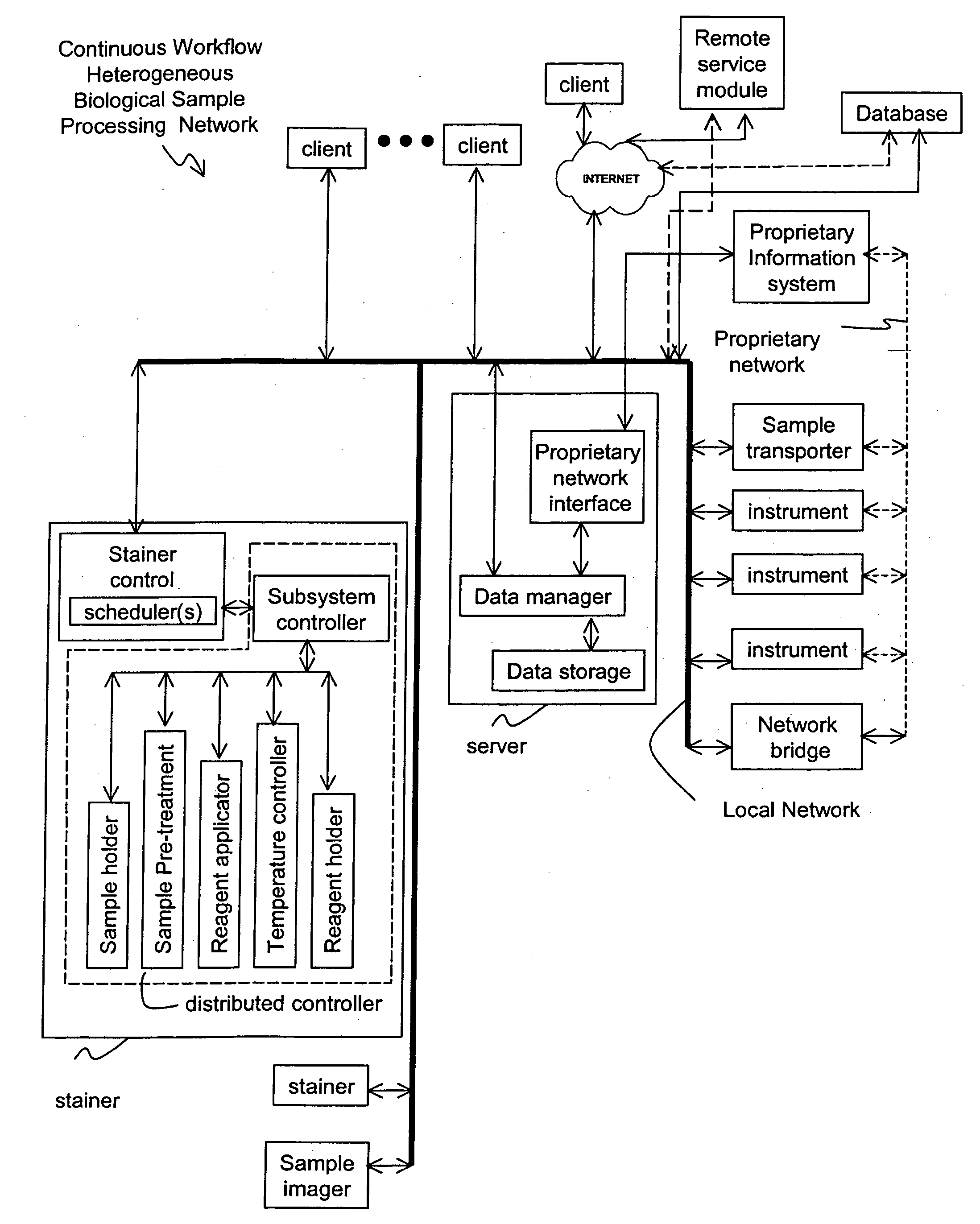
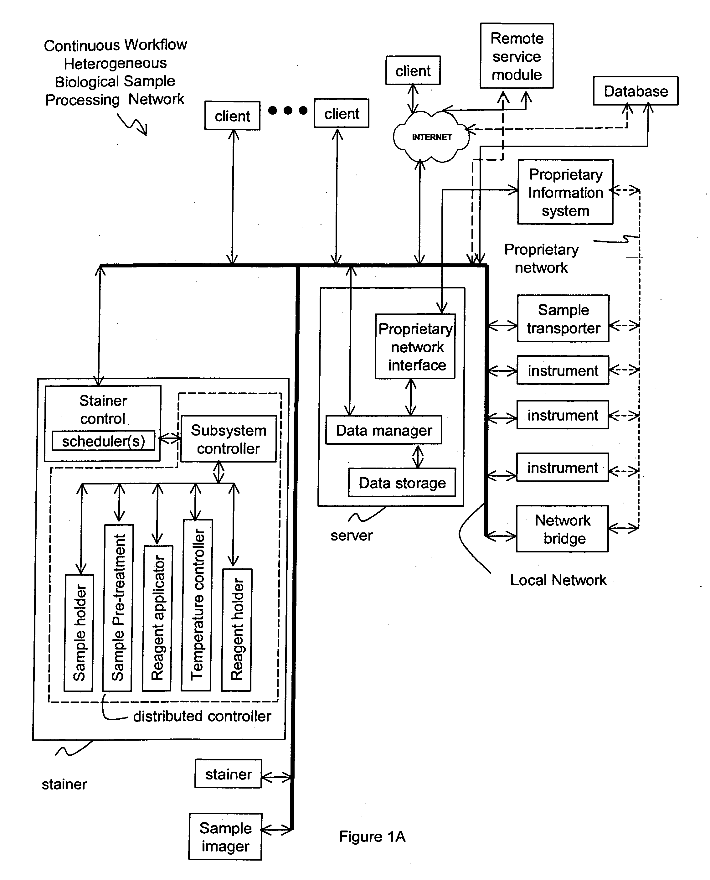
computer control and monitoring of sample processing; the lack of
information sharing for processing protocol and processing status, especially for individual samples; the lack of diagnostic capabilities; and the lack of real-time or adaptive capabilities for multiple sample group processing.
The
staining procedure may be laborious and use many different reagents.
However, in some applications, such mixing processes have been cumbersome.
Thus, some existing systems may have disadvantages in their implementation of mixing processes, for example, due to the complex use of reagents in the
staining procedure.
Furthermore, the resulting mixtures are unstable over time and need to be used within a short time.
Many proteins cannot easily tolerate to be exposed to the hydrophobic air in foam.
The foam can spread to other compartments of the instrument in an unwanted and unpredictable way.
Mixing of some reagents (e.g. the HRP chromogens and
peroxide reagents) can result in the formation of small bubbles.
Spill over / carry over is often undesirable.
Some of the reagents or buffers are incompatible with each other.
In the event of cross
contamination due to e.g. carry over, the reagents may be ruined within seconds or solids can precipitate, making the
staining unsuccessful.
For example,
enzyme containing reagents can not be mixed with the corresponding chromogens, or high salt concentrates may not be mixed with e.g. proteins containing mixtures, or organic solvents can not be mixed with
protein containing mixtures, or highly pH buffered wash buffers can not be mixed with low buffered mixtures without significantly altering the properties of the reagents.
As some procedures may be regarded as complex, existing instruments may use many different protocols resulting in less predictable results due to even minute amounts of
reagent carry-over or unplanned mixing of reagents.
During staining, build-up of small
fouling layers on the various surfaces may cause problems, as the typical staining protocol calls for many mixing and
dilution steps.
At least some present mixing systems for automated biological sample processing do not truly fulfill one or more of the above-mentioned properties.
On-the-slide mixing may not allow for very large ratios of
dilution.
It may also not allow for efficient mixing of reagents with very different densities or viscosities.
However, each of these traditional sample processing systems may lack a desired degree of
temperature control or temperature tolerances.
Inadequacies in
temperature control of traditional technologies may include uncontrolled cooling.
Traditional systems may only provide ambient cooling when the heating devices are off.
Ambient cooling is not considered
active control and may not meet protocol temperature requirements or may not otherwise be optimal.
Although heating and
heat control may be features of such systems, controlled cooling of the samples, sample carriers, and processing environments may not always be adequately addressed.
However, these devices can lack sufficient capabilities of
temperature control to meet certain protocol requirements, especially temperature tolerances for samples, sample carriers, reagents, and ambient
system temperature.
Traditional systems may even lack temperature control, perhaps as related to temperature tolerances generally, as such tolerances may not be adequately maintained during ambient or other traditional cooling, or during processing sequences or events, generally.
In some protocols, for example, the temperature tolerances during non-heating periods may be such that uncontrolled temperature changes may produce undesirable results during the processing sequence.
Other IHC processes of the protocol may be adversely affected by uncontrolled temperature changes, the degree of temperature change, and temperature changes outside of acceptable tolerances.
The lack of temperature control may actually dissuade technologists from employing automated processing sequences or protocols, especially IHC sequences, that may be dependent upon a particular temperature tolerance and the amount of temperature change during a processing sequence.
Certain types of temperature control may not have even been addressed in traditional sample processing
system technologies.
Reagents, for example, can have a certain
shelf life that may be limited if maintained at undesirable temperatures such as the typical ambient temperatures of traditional biological sample processing systems and the laboratories-housing such systems.
Traditional technologies may lack the temperature control needed to optimally preserve the reagents stored in the processing system that are often subject to inadequate or changing ambient temperatures of such systems and the laboratory environment.
Currently available biological staining apparatuses do not provide for sample pre-treatment.
Unfortunately, however, this manual preparation may be cumbersome and the pre-treatment may be insufficient, since the amount of time and the temperature of the liquid should be observed substantially precisely in order to achieve the correct pre-treatment result.
Preparation of the aforementioned pre-treatment processes and the like may be difficult to achieve via manual preparation.
However this instrument does not provide a processing tank for pre-treatment of the slides.
However, this does not sufficiently protect the laboratory environment in which the apparatus is placed from being contaminated with
toxic material.
This increases the risk of vaporizing reagents which then may escape to the outside of the apparatus.
In this known technique, one may risk the
drying out of slides and lack of control of
airspeed and temperature.
Hence, some conventional apparatuses hitherto have not provided for adequate sample pre-treatment.
Manual
sample preparation may be cumbersome because pre-treatment steps are often subject to stringent constraints and are sensitive to minute variations in experimental conditions.
Additionally, on account of the sensitive nature of the process, there is a need to provide feedback to users about processing related errors, or a lack of resources in
sufficient time for corrective action to be taken.

