Modular fabrication systems and methods

Active Publication Date: 2006-07-20
CORNELL RES FOUNDATION INC
View PDF34 Cites 239 Cited by
  • Summary
  • Abstract
  • Description
  • Claims
  • Application Information

AI Technical Summary

Benefits of technology

[0014] The system may also have a device to automatically switch tools and their cartridges and substrate modules, or these may be fixed in the system. A system controller is operably connected to the material tools, cartridges, substrate modules, transfer devices, and positioning systems. The system has provision for monitoring and controlling the environmental conditions under which fabrication takes place, for monitoring and correcting fabrication errors during the course of fabrication, and for monitoring and controlling the properties of the article being fabricated during the course of fabrication. The combined capabilities of the system, the deposition tools, and the substrate modules allow monitoring and control of the conditions experienced by all of the materials and by the article being fabricated, before, during, and/or after the fabrication process. This extends the freeform fabrication process to include controlled evolution of material properties as well as controlled deposition of multiple materials, allowing not just geometric,

Problems solved by technology

Together, these two properties mean that SFF processes are subject to very different constraints than traditional material removal-based manufacturing.
On the other hand, a deposition process must be developed and tuned for each material, geometry is limited by the ability of the deposited material to support itself and by the (often poor) resolution and accuracy of the process, and multiple material and process interactions must be understood.
All of these systems still depend upon a small fixed set of deposition process technologies, and are therefore limited to the materials which can be adapted to those processes, by the effects of those particular processes on the materials, and by the fabrication rates and resolutions of those processes.
In addition, this system has only demonstrated fabrication of thin films of materials—its ability to deposit many layers of materials is not well established.
In addition, none of these systems explicitly measures the properties of, and monitors and controls the

Method used


Image

  • Modular fabrication systems and methods
  • Modular fabrication systems and methods
  • Modular fabrication systems and methods

Examples


Example

Example 1

Direct Freeform Fabrication of Living Pre-Cell-Seeded Alginate Hydrogel Implants in Anatomic Shapes

[0150] Articular chondrocytes were isolated from cartilage from the femeropatellar groove of 1-2 week old calves by collagenase digestion (Genes et al., “Effect of Substrate Mechanics on Chondrocyte Adhesion to Modified Alginate Surfaces,”Arch. Biochem. Biophys. 422:161-167 (2004), which is hereby incorporated by reference in its entirety). Chondrocytes were suspended in 2% ultrapure low viscosity alginate in phenobarbital sodium (“PBS”) at a concentration of 50 million cells / mL. The suspension was vortexed and mixed with 10 mg / mL CaSO4 in PBS in a 2:1 ratio. The gel was placed in a sterile 10 mL syringe with a 22 gauge SafetyLok tapered syringe tip and loaded into a gel deposition tool.

[0151] In parallel, a computerized tomography (“CT”) scan of an ovine meniscus was converted into a stereolithography file using Microview software. The file was then imported into a custom ...

Example

Example 2

Direct Freeform Fabrication of Spatially Heterogeneous Living Cell-Impregnated Implants

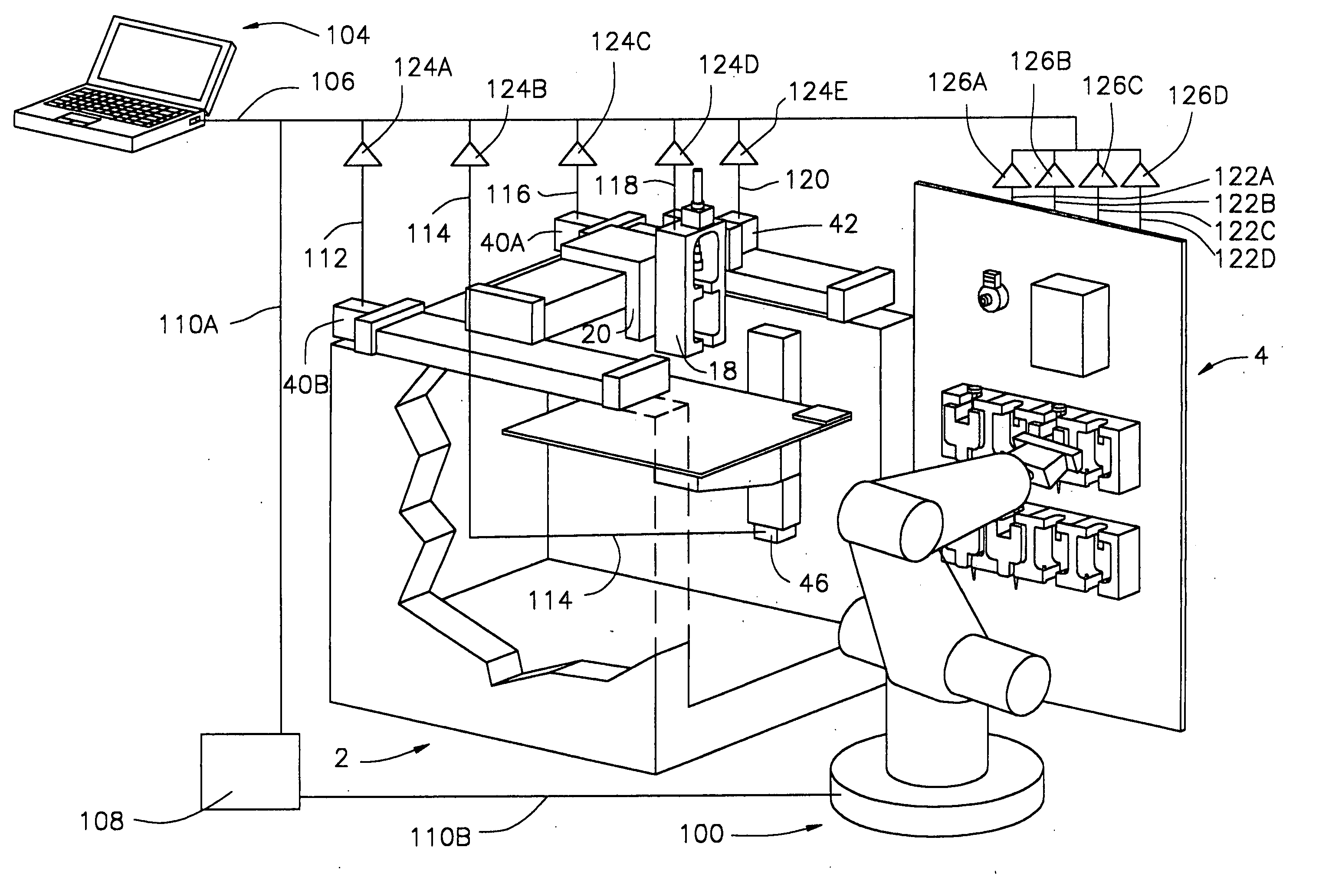
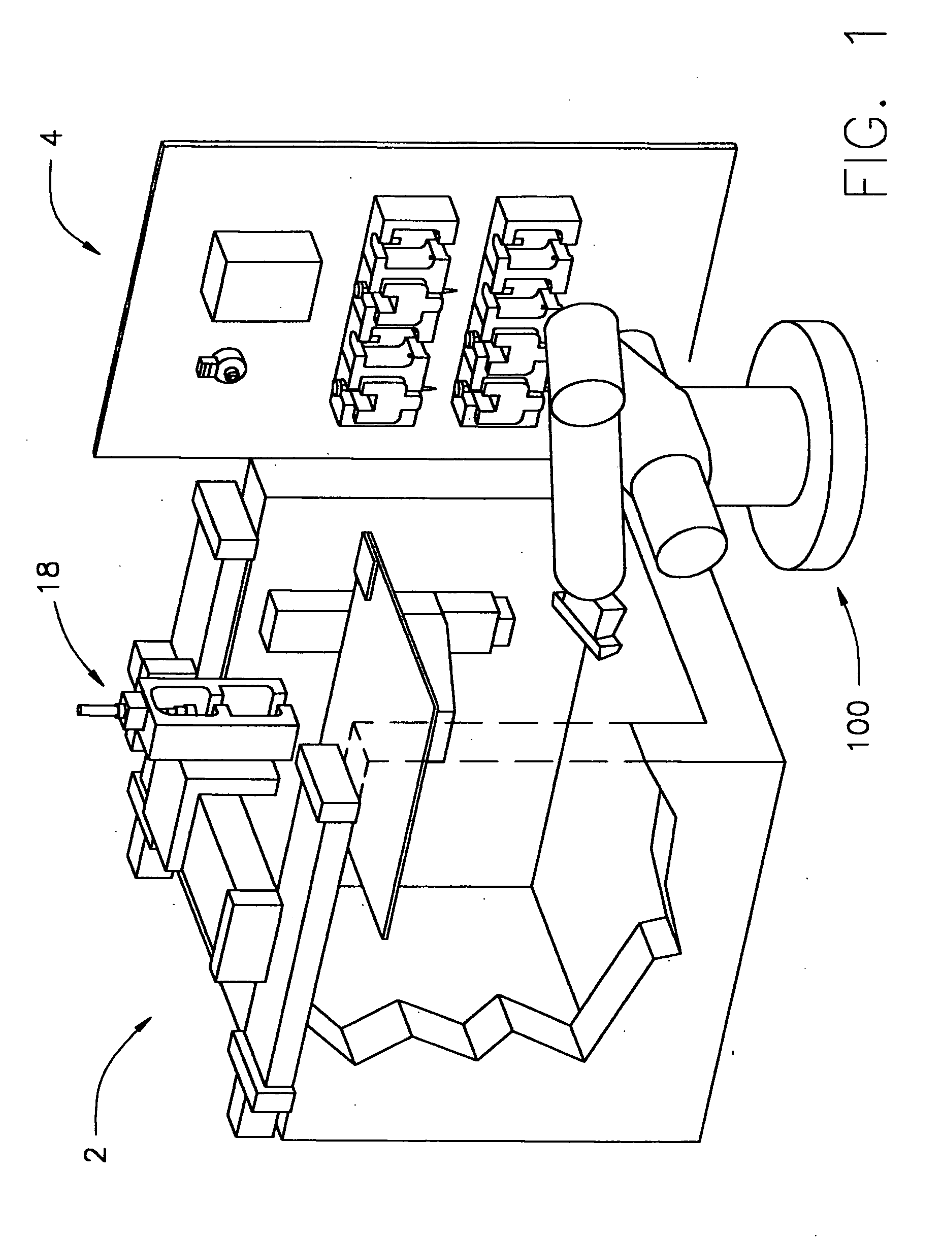
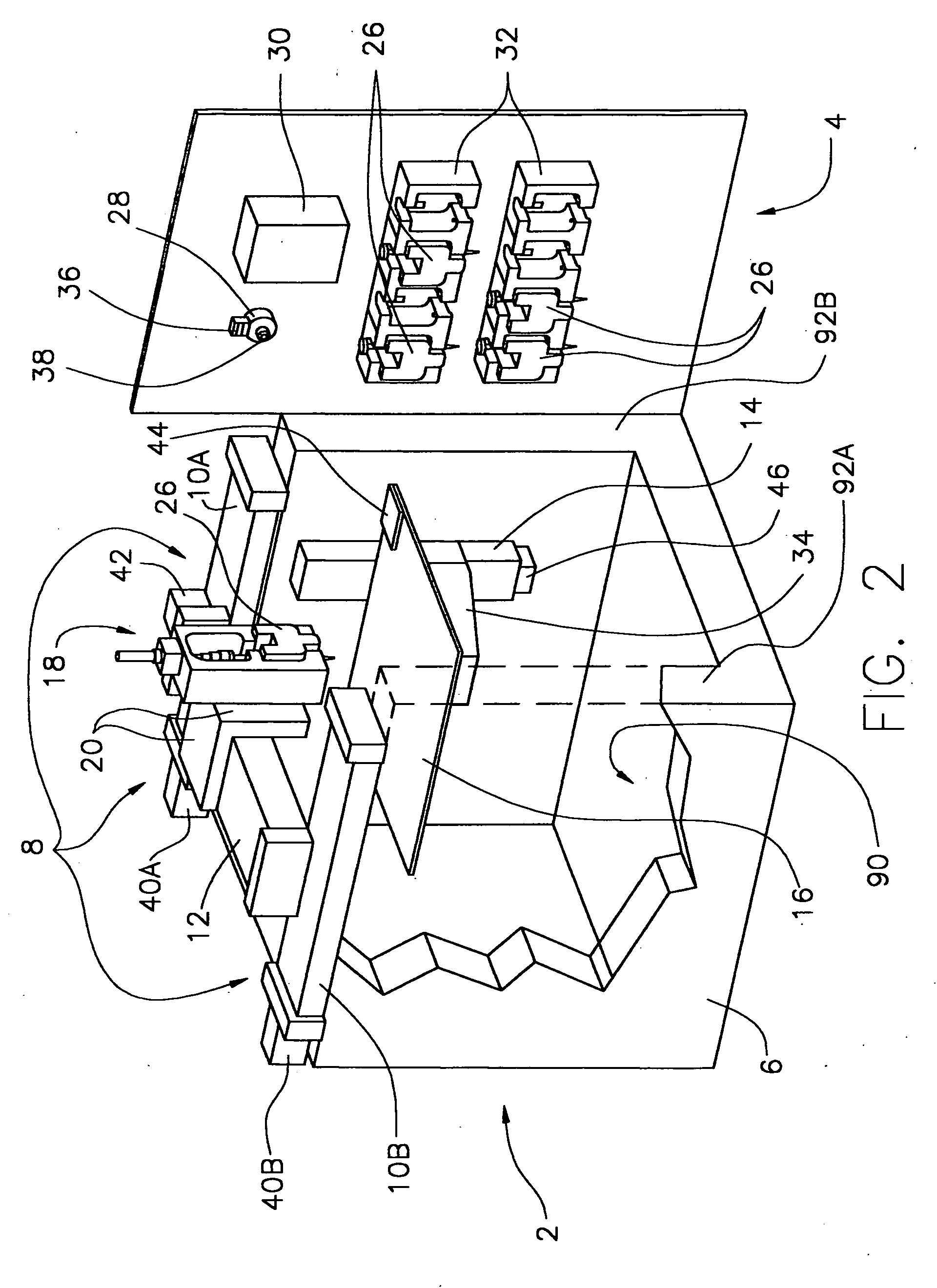
Robotic Test Platform

[0158] An open-architecture gantry robot has been designed and used in this research (Malone et al., “Freeform Fabrication of 3D Zinc-air Batteries and Functional Electro-mechanical Assemblies,”Rapid Prototyping Journal 10:58-69 (2004), which is hereby incorporated by reference in its entirety). The tool paths are generated by path planning software, which takes multiple stereo lithography files corresponding to multiple material types as input. This system has been designed to allow the printing of multiple materials within a single part. This capability is used to print multiple gels with varying cell types, chemical concentrations, cell densities, etc. The robot is capable of moving the deposition tool to a specified position with accuracy and repeatability of ±25 μm. The full specifications of this robotic system are given in Table 1. TABLE 1Fabrication Syste...

Example

Example 3

Direct Freeform Fabrication of Zinc-Air Batteries with Tailored Geometry and Performance

[0181] In the following discussion, a cell is defined as a device that converts the chemical potential energy between its anode and cathode materials into electrical energy by means of redox reactions: reduction (electron gain) at the cathode, oxidation (electron loss) at the anode. A battery comprises of one or more connected cells. The essential functional components of a zinc-air (“Zn-air”) cell are the anode terminal, cathode terminal, anode, separator, catalyst, electrolyte, and casing. The anode and cathode terminals are passive conductors that collect charge carriers and allow connection to external loads. The anode (zinc in this case) is one of the two key reactants in the cell. The other key reactant, oxygen, is derived directly from the atmosphere. The separator provides electrical insulation between the anode and cathode to prevent internal shorting, but must be permeable to...


PUM

PropertyMeasurementUnit
Volumeaaaaaaaaaa
Volumeaaaaaaaaaa
Volumeaaaaaaaaaa

Abstract

The present invention relates to an article fabrication system having a plurality of material deposition tools containing one or more materials useful in fabricating the article, and a material deposition device having a tool interface for receiving one of the material deposition tools. A system controller is operably connected to the material deposition device to control operation of the material deposition device. Also disclosed is a method of fabricating an article using the system of the invention and a method of fabricating a living three-dimensional structure.

Description

[0001] This application claims the priority benefit of the provisional patent application entitled, “Modular Fabrication Systems and Methods,” filed Aug. 1, 2005, with express mail certificate number EV652971121US and U.S. Provisional Patent Application Ser. No. 60 / 600,529, filed Aug. 11, 2004, which are hereby incorporated by reference in their entirety.FIELD OF THE INVENTION [0002] The present invention relates generally to an article fabrication system, a method of fabricating an article, and a method of fabricating a living three-dimensional structure. BACKGROUND OF THE INVENTION [0003] Solid freeform fabrication (“SFF”) is the name given to a class of manufacturing methods which allow the fabrication of three-dimensional structures directly from computer-aided design (“CAD”) data. SFF processes are generally additive, in that material is selectively deposited to construct the product rather than removed from a block or billet. Most SFF processes are also layered, meaning that a...

Claims


Application Information

Patent Timeline
IPC IPC(8): H01L21/00B05C11/00
CPCB29C67/0055A61L27/36B33Y10/00A61L2430/10B33Y70/00A61L27/3817A61L27/52B33Y50/02B33Y30/00B33Y50/00B33Y40/00B33Y80/00B29C64/118B29C64/393B29C64/106A23P2020/253B22F10/18B22F12/50B22F12/30B22F12/82B22F12/90B22F12/38Y02P10/25B29C64/386A61L27/20A61L27/44A61L27/54B29L2031/7532
Inventor LIPSON, HODBONASSAR, LAWRENCECOHEN, DANIEL L.MALONE, EVAN
Owner CORNELL RES FOUNDATION INC
Why Eureka
Try Eureka