Electric converter for fuel cell

Inactive Publication Date: 2006-08-03
COMMISSARIAT A LENERGIE ATOMIQUE ET AUX ENERGIES ALTERNATIVES
View PDF11 Cites 7 Cited by
  • Summary
  • Abstract
  • Description
  • Claims
  • Application Information

AI Technical Summary

Benefits of technology

[0062] The electric converter for fuel cell according to the invention has numerous advantages.
[0079] The electric converter of the invention also comprises rectifying means with diodes. The diodes of the rectifying means are mounted in series or in the form of a diode matrix. This makes it possible to use standard industrial components offering fast speed. The speed of a diode is characterized by its reverse recovery time, i.e. the time during which the diode allows the current to pass in reverse and is not yet able to block it. This phase gives rise to many losses. Reverse recovery time is greater the higher the voltage withstand strength of the diode is. The placing in series or in a matrix of diodes having a low voltage withstand strength instead of a single diode for example having a high voltage withstand strength, enables a relatively short reverse recovery time to be obtained which is the time of diodes having low voltage withstand strength. This is an advantage for reducing losses and allows functioning at a higher frequency to increase compactness.

Problems solved by technology

In applications for vehicles or stationary generators, the electric energy produced is not directly adapted for use.
Firstly the fuel cell does not provide a constant voltage, and secondly the produced voltage is low.
This physical phenomenon is more detrimental the more the operating voltage of the motor is low.
Electric power supplied in the form of low voltage and strong current is also a major constraint with respect to the sizing and losses of the brushes and collector rings or of the electronic converter performing this function.
The standardisation of applications in the two above cases is due to the physical limitations set forth above, which translate as poor performance for high-power motors supplied with low voltages (typically less than 100 volts) and to the existence of effective industrial solutions for motors and inverters supplied by electric grids.
In practice, the technical constraints relating to voltage, current and switch losses limit the use of the step-up chopper assembly to step-up coefficients in the order of two or three.
A step-up chopper stage cannot ensure short-circuiting protection for the fuel cell.
A short circuit at the output of the step-up chopper translates as short-circuiting of the fuel cell which it may not be able to withstand.
Increasing the frequency of a step-up chopper is limited by the strong constraints on the switch and diode which are sized both for the highest voltage and for the strongest current, and is limited by the technological difficulties involved in producing strong current inductors operating at high frequency.
On account of the voltage and current constraints of switches and diodes, an increase in frequency rapidly translates as a substantial increase in the switching losses of these components.
Part of this energy is located in the winding of the element and gives rise to eddy current copper losses.
High power, strong current inductors are technically difficult to fabricate due to these eddy current losses.
These difficulties are heightened when raising the frequency of the assembly.
This over-sizing is a heavy constraint for the converter, translating as an increase in its weight, volume and hence cost, and as an increase in its losses and hence a drop in its yield.

Method used


Image

  • Electric converter for fuel cell
  • Electric converter for fuel cell
  • Electric converter for fuel cell

Examples


first embodiment

[0088]FIG. 8 shows a first example of an electric converter for fuel cell according to the invention;

[0089]FIG. 9 shows a second example of an electric converter for fuel cell according to the first embodiment of the invention;

second embodiment

[0090]FIG. 10 shows an electric converter for fuel cell according to the invention;

third embodiment

[0091]FIG. 11 shows an electric converter for fuel cell according to the invention.

DETAILED DESCRIPTION OF EMBODIMENTS OF THE INVENTION

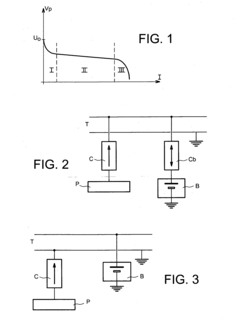
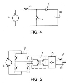
[0092] FIGS. 1 to 5 were described previously, no further description is necessary.

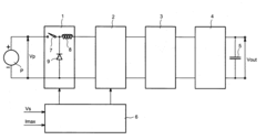
[0093]FIG. 6 is a diagram showing the principle of the electric converter for fuel cell according to the invention, and FIG. 7 shows the output voltage Vout of an electric converter for fuel cell according to the invention in relation to the current I delivered at the output of the current inverter means.

[0094] The converter comprises a voltage step-down chopper 1, a current inverter 2, a transformer 3, a rectifier 4, a filtering capacitor 5 and a command circuit 6. The voltage step-down chopper 1 comprises, for example, a switch 7, a self-inductor 8 and a diode 9. The command circuit 6 pilots the switch of the step-down chopper and the switches (not shown FIG. 6) of the current inverter 2. A set threshold voltage Vs and a set maximum current Imax are applied to the...


PUM


Abstract

The invention concerns an electric converter for fuel cell (P) comprising current inverter means (2), the electric converter comprising a voltage step-down chopper (1) mounted between the fuel cell (P) and the current inverter means (2), wherein, under the action of a command signal applied to the voltage step-down chopper (1): the value of the mean voltage at the input of the current inverter means is lowered to a threshold value (Vs) in the cell electrode activation zone, the value of the mean voltage at the input of the current inverter means (2) is maintained at the voltage value at the cell terminals (Vp) in the cell resistance zone, and the output current of the converter is limited when the output current from the current inverter means (2) reaches a maximum set value (Imax).

Description

TECHNICAL AREA AND PRIOR ART [0001] The invention pertains to an electric converter for fuel cell. [0002] Fuel cells are used as electric power source in numerous applications. [0003] Among others, they are proposed as power source in electric motor vehicles (cars, buses, electrically propelled boats, etc.) to replace internal combustion engines. This makes it possible to reduce local pollution generated by motor vehicles. [0004] A fuel cell is an electrochemical generator whose electrodes are continuously supplied with fuel and oxidant. For application to motor vehicles, the technology chosen is chiefly PEMFC technology i.e. Proton Exchange Membrane Fuel Cells supplied with hydrogen and with oxygen from air. [0005] The hydrogen used may be stored in a tank onboard the vehicle. In this case it is hydrogen that is used as energy vector in chemical form. The fuel cell converts this chemical energy into the electric energy required by the vehicle's electric motors. [0006] The hydrogen ...

Claims


Application Information

Patent Timeline
IPC IPC(8): H03M7/00H02M1/00H02M3/156
CPCH02J2001/004H02M3/156H02M2001/007H02M2001/0087H02J2300/30H02M1/007H02M1/0087
InventorCHATROUX, DANIELMARC, SEVERINELAUSENAZ, YVAN
OwnerCOMMISSARIAT A LENERGIE ATOMIQUE ET AUX ENERGIES ALTERNATIVES