Deactivated surfaces for chromatographic separations and methods of making and using the same

Inactive Publication Date: 2006-08-10
AGILENT TECH INC
View PDF6 Cites 14 Cited by
  • Summary
  • Abstract
  • Description
  • Claims
  • Application Information

AI Technical Summary

Benefits of technology

[0005] In one embodiment, the invention provides deactivated surfaces (e.g., columns or channels) for use in chromatographic separation techniques. The deactivated surfaces comprise an inner surface material (e.g., such as glass or fused silica) coated with a polymer layer (“deactivation polymer”) that sterically hinders interactions between components in a sample coming in contact with the polymer layer and reactive silanols present on the inner surface. In one aspect, the de

Problems solved by technology

If the active sites on the surface of the column are not eliminated, the chromatographic analyte reacts with the active sites and distorts or even invalidates the results of the chromatography.
In this respect, the prior art has only been partly successful in developing satisfactory deactivation procedures, and the procedures that have been developed are often narrowly limited in success.
For example, high temperature (>320° C.) silylation surface deact

Method used


Image

  • Deactivated surfaces for chromatographic separations and methods of making and using the same
  • Deactivated surfaces for chromatographic separations and methods of making and using the same
  • Deactivated surfaces for chromatographic separations and methods of making and using the same

Examples


example 1

Method Of Synthesizing A Polyalkylhydrosiloxane Composition

[0054] To a solvent mixture consisting of 15 mL of methylene chloride and 15 mL of acetonitrile is added 3.00 mL (2.98 g) of tetramethylcyclotetrasiloxane (which will be equivalent to 77.8 mole percent methylsilylhydride content in the final polysiloxane) and 0.400 g Amberlyst 15 (resin bound sulfonic acid catalyst)(Aldrich Chemical, Milwaukee, Wis., USA). This mixture is typically stirred for approximately 5 hours at room temperature.

[0055] This results in a polymethylhydrosiloxane.

[0056] Then 2.05 mL (2.02 g or 22.2 mole percent relative to the methylsilylhydride content) diphenyltetramethyldisiloxane is added and the mixture is stirred for an additional 12 to 16 hours. The solution is then filtered to remove the catalyst resin. The solvents are removed using a rotary evaporator and the resulting polymer is used with no further purification.

[0057] This results in a phenyldimethylsilyl end capped polymethylhydrosiloxane...

example 2

Preparing a Deactivated Surface

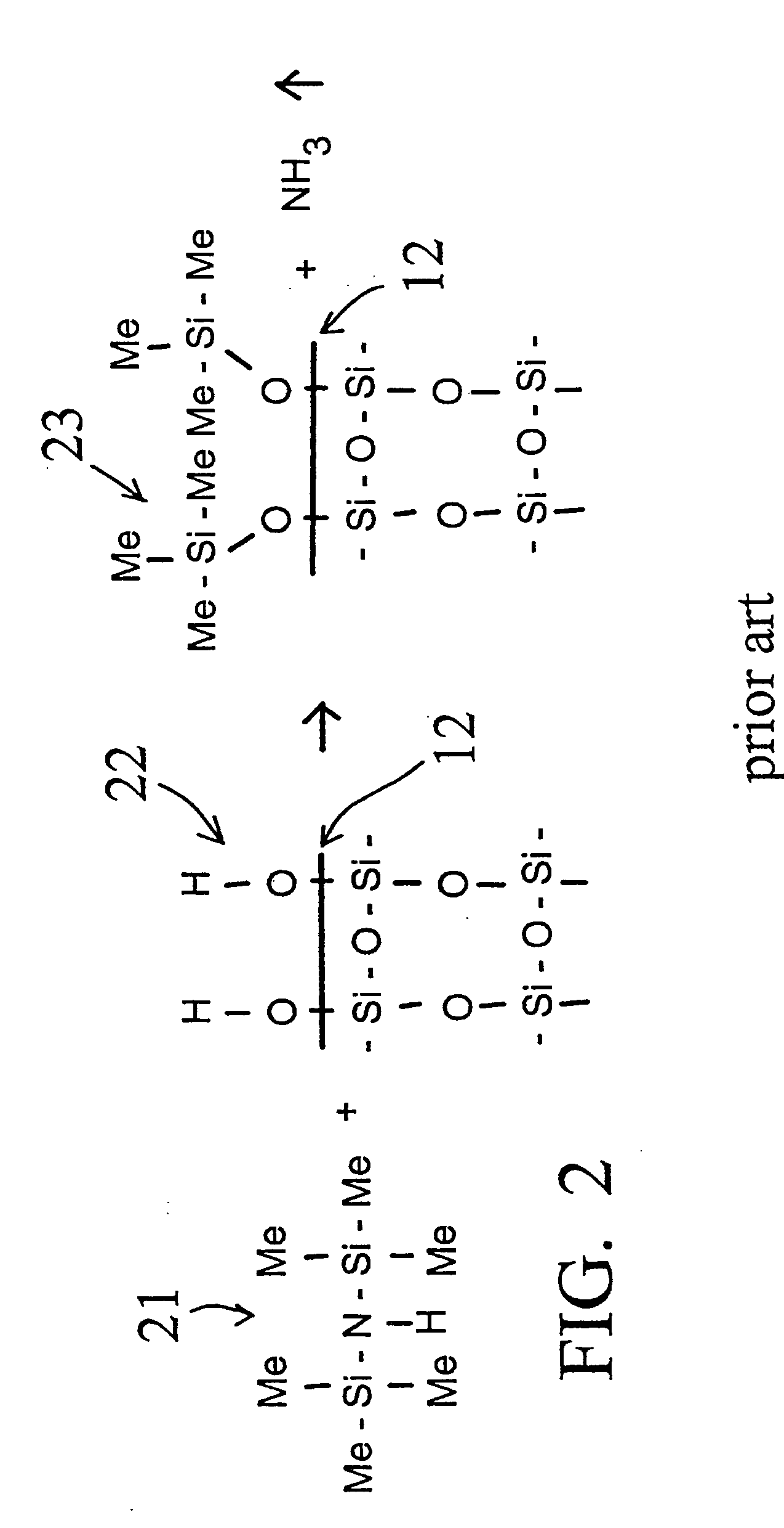
[0058] A deactivation reaction between a surface to be deactivated and a deactivation polymer is shown in FIG. 3 and FIG. 4, with FIG. 2 showing a commercially available prior art alternative “persilylation” reaction. In FIG. 2, the prior art process reacts a disilazane 21 with the silanols 22 on the surface 12 of the glass or fused silica wall. The result is the formation of trimethylsilyl capping groups 23 on the glass surface 12, and the release of ammonia.

[0059]FIG. 3 shows an example of an embodiment of this invention. Phenyldimethylsilyl end capped polymethylhydrosiloxane 26, reacts with the silanols 22 on the surface 12 of the glass or fused silica wall. The result is the formation of a phenyldimethylsilyl end capped polymethylsilyl layer 24 on the glass surface 12, and the release of hydrogen. The deactivation polymer layer 24 is stable and provides continuous coverage of the glass surface 12, and, because of the polar end caps, provides a hi...

example 3

Method of Using a Deactivated Surface

[0063] In order to compare a capillary column comprising a deactivated surface according to the invention to a conventional commercially available disilazane deactivated capillary column (using the chemistry of FIG. 2), a test mix was run through each column. The test mix compounds are, in order of elution, 1) 2-Ethylhexanoic acid, 2) 1,6-Hexanediol, 3) 4-ChlorophenoJl, 4) Tridecane, 5) 1-Methylnaphthalene, 6) 1-Undecanol, 7) Tetradecane, 8) Dicyclohexylamine.

[0064] The chromatogram shown in FIG. 5 illustrates the output of a typical deactivated column produced by a current commercially used production process using the chemistry of FIG. 2. Note the “tailing” (skewing of peak at near the baseline of right shoulder) of peaks number 1, 2, and 3.

[0065] The chromatogram shown in FIG. 6 illustrates the output of a deactivated column comprising a polar group end capped hydrosiloxane deactivated capillary tubing using the chemistry of FIG. 3. The sam...


PUM

PropertyMeasurementUnit
Velocityaaaaaaaaaa
Surface energyaaaaaaaaaa
Chemical structureaaaaaaaaaa

Abstract

Disclosed are deactivated surfaces for use in chromatographic separations, such as capillary gas chromatography, comprising a surface material coated with a deactivating polymer comprising high surface energy-generating groups and groups for end-capping reactive silanols. Also disclosed are columns comprising such surfaces, methods of making and using the surfaces, and kits for facilitating the same.

Description

BACKGROUND [0001] Gas chromatography is a technique for fractionating and determining the relative amounts of various components in a sample containing a mixture of components of differing volatilities. Generally, a sample is vaporized and the resulting gases are passed through an analytical chromatography column and separated components are detected. To increase separation efficiency and increase sensitivity, chromatography is often performed using capillary columns comprising a chromatographically active stationary phase. The chemistry of the stationary phase is designed to cause different types of molecules to pass through a column at different times and under different conditions, resulting in the separation of molecules as a complex sample passes through the column. [0002] A separation technique relying on capillary columns is capillary gas chromatography (GC). Capillary GC is a separation technique in which the vapor phase of a sample in a gaseous, mobile phase passes through ...

Claims


Application Information

Patent Timeline
IPC IPC(8): B01D15/08
CPCB01D15/206B01D15/22B01J20/286B01J2220/54B01J2220/86C08G77/12G01N30/6073G01N30/6078G01N2030/567B01J20/3272
Inventor LAUTAMO, ROY M.A.
Owner AGILENT TECH INC
Why Eureka
Try Eureka