Composite material

a composite material and composite material technology, applied in the field of new composite materials, can solve the problems of increasing affecting peripheral equipment, malfunction of devices, and material types, and achieve the effect of improving physical properties

Inactive Publication Date: 2006-09-28
HODOGOYA CHEMICAL CO LTD
View PDF2 Cites 17 Cited by
  • Summary
  • Abstract
  • Description
  • Claims
  • Application Information

AI Technical Summary

Benefits of technology

[0014] Therefore, this invention aims to provide new composite materials capable of solving some or all of above mentioned problems. This invention also aims to provide composite materials having improved physical properties, such as electrical, mechanical and thermal properties, without significantly damaging the innate characteristics of the matrix. These composite materials are prepared by using a small amount of new carbon fibrous structures that have physical properties suitable for use as fillers in composite preparations.

Problems solved by technology

As various electronic devices increases, problems such as malfunction of devices caused by static electricity and electromagnetic wave interference caused by noises from certain electronic components affect peripheral equipments are also on the rise.
However, there are several drawbacks in these types of materials.
For example, when using metallic fibers and metallic powders as the conductive filler, the materials thus obtained have poor corrosion resistance and mechanical strength.
When using carbon fibers as the conductive filler, although a predetermined strength and elastic modulus may be obtained by adding relatively large amounts of the filler, electrical conductivity generally cannot be greatly enhanced by this approach.
If one attempts to attain a predetermined conductivity by adding a large amount of filler, one would invariably degrade the intrinsic properties of the original resin material.
In such manufacturing processes, the level of material loss during carbonization is high and the carbonization rate is slow.
Therefore, carbon fibers made by these processes tend to be expensive.
On the other hand, however, such fine carbon fibers unfortunately show an aggregate state even just after their synthesis.
When these aggregates are used as-is, the fine carbon fibers would be poorly dispersed into the matrix, and thus the product obtained would not benefit from the desired properties of the nano structures.
Thus, they do not fulfill the need for ideal additives that are capable of improving various characteristics of a matrix, such as electrical conductivity, at small dosages.
Since the fixing of carbon fibers is performed by such a heat treatment after synthesis of the carbon fibers, the affixing forces at the contacting points are weak and do not result in good electrical properties of the carbon fibrous structures.
When these carbon fibrous structures are added to a matrix such as a resin, the carbon fibers fixed at the contacting points are easily detached from each other, and the carbon fibrous structures are no longer maintained in the matrix.
Therefore, it is not possible to construct preferable conductive paths in a matrix such that good electrical properties may be conferred on the matrix by a small additive amount of the carbon fibrous structures.
Furthermore, when a binder is added to promote fixing and carbonization at the contacting points, fibers in the obtained fibrous structures would have large diameters and inferior surface characteristics because the added binder is attached to the whole surface areas of the fibers rather than to limited areas on the contacting points.

Method used


Image

  • Composite material
  • Composite material
  • Composite material

Examples


synthetic example 1

[0102] By the CVD process, carbon fibrous structures were synthesized using toluene as a raw material.

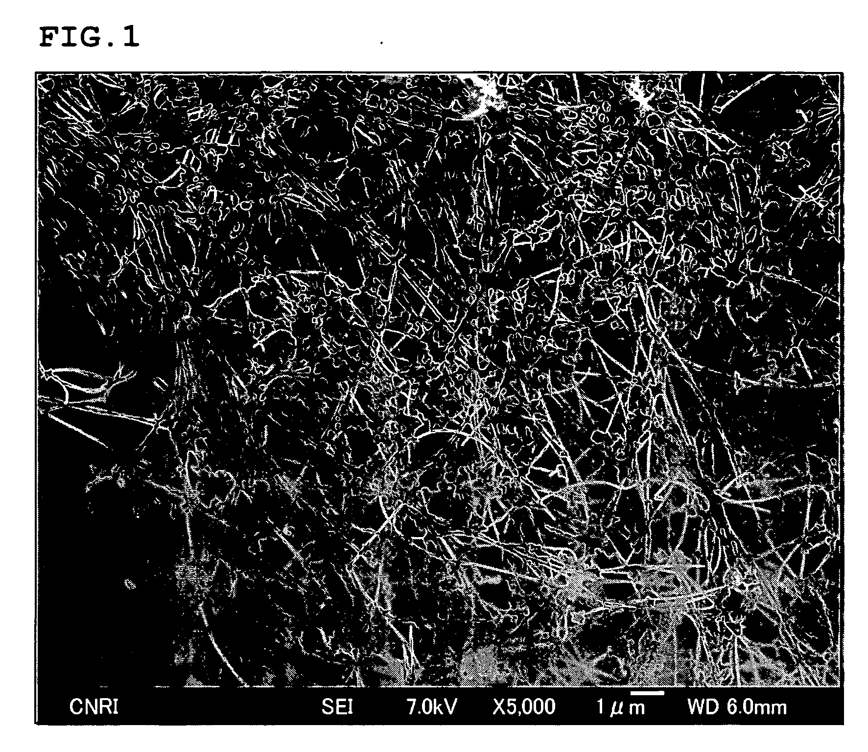
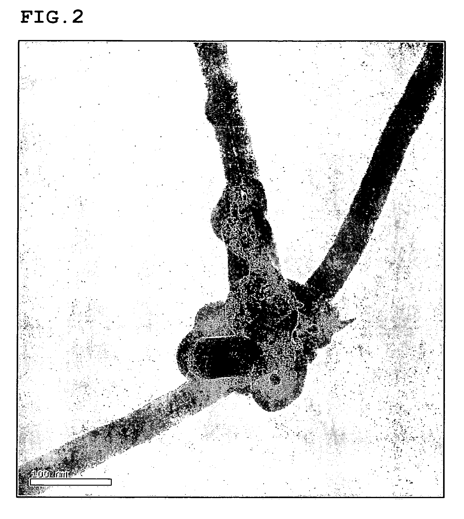
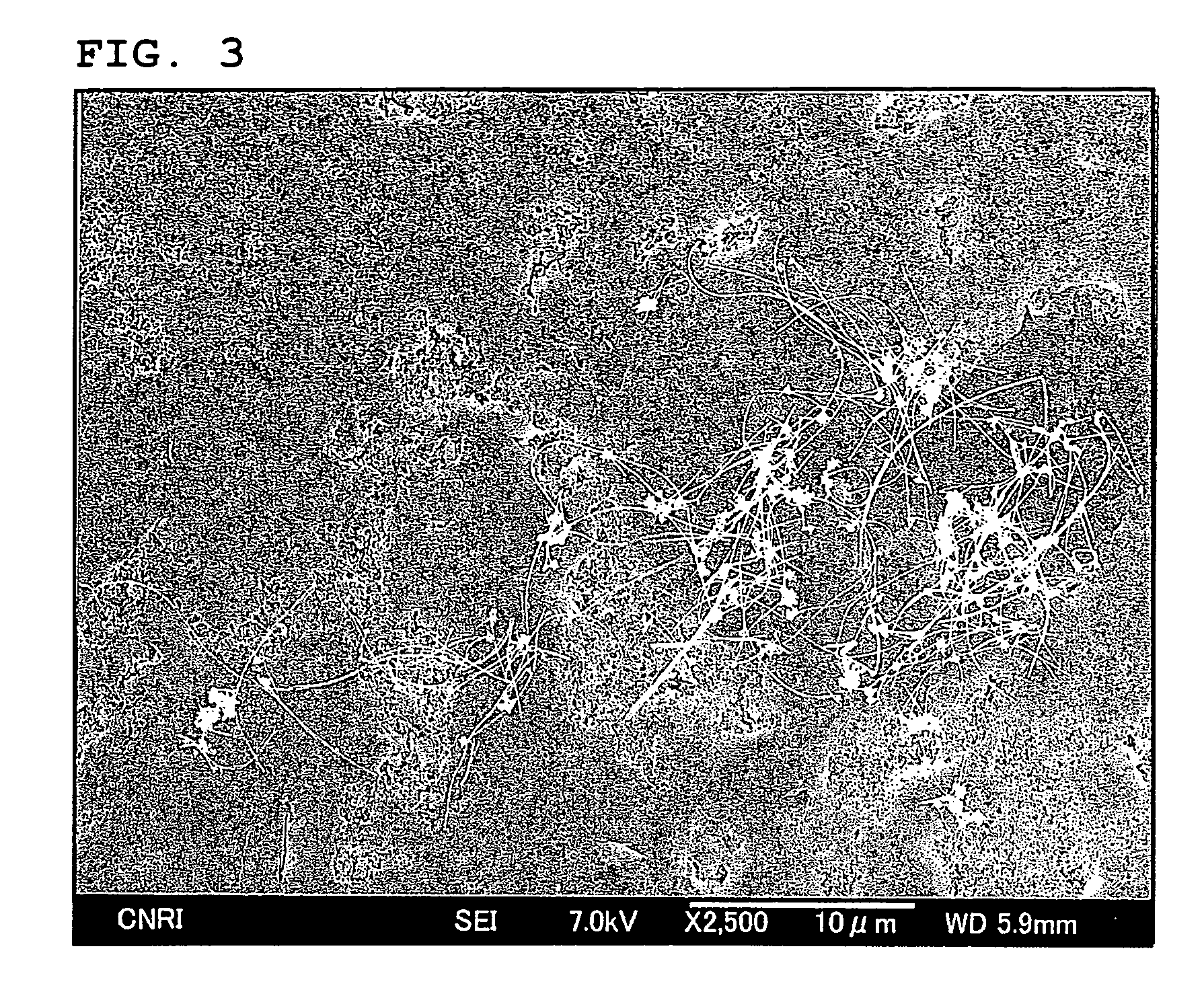
[0103] The synthesis was carried out in the presence of a mixture of ferrocene and thiophene as the catalyst, and under the reducing atmosphere of hydrogen gas. Toluene and the catalyst were heated to 380° C. along with the hydrogen gas, and then they were supplied to the generation furnace, and underwent thermal decomposition at 1250° C. in order to obtain the carbon fibrous structures (first intermediate). The synthesized first intermediate was baked at 900° C. in nitrogen gas in order to remove hydrocarbons such as tar to obtain a second intermediate. The R value of the second intermediate measured by the Raman spectroscopic analysis was found to be 0.98. Sample for electron microscopes was prepared by dispersing the first intermediate into toluene. FIGS. 1 and 2 show SEM photo and TEM photo of the sample, respectively.

[0104] Further, the second intermediate underwent a high te...

examples 1-7

[0110] Epoxy type adhesive compositions were prepared according to the formulations shown in Table 3, by blending the carbon fibrous structures obtained in Synthetic Example 1 with an epoxy resin (ADEKA RESIN™, manufactured by Asahi Denka Co., Ltd.) and a hardener (ADEKA HARDENER™, manufactured by Asahi Denka Co., Ltd.), and then kneading them with a rotation-revolution type centrifugal mixer (Awatori-NERITARO, manufactured by Thinky Co., Ltd.) for ten minutes.

[0111] Each epoxy type adhesive compositions thus obtained were applied on a glass plate using an applicator having a coating width of 100 mm and gap of 200 μm. The coated film was then hardened at 170° C. for 30 minutes to obtain a hardened film. The hardened film was then cut up into 50 mm×50 mm test pieces. Using the test pieces, volume resistivity and thermal conductivity were determined. The results obtained are shown in Table 3.

[0112] A similar epoxy resin composite film was prepared in a similar manner, except that th...

examples 8-13

[0116] Resin pellets were prepared according to the formulations shown in Table 5, by blending the carbon fibrous structures obtained in Synthetic Example 1 with a polycarbonate resin (Panlite® L-1225L, manufactured by Teijin Chemicals Ltd.) or a polyamide resin (Leona™ 1300S, manufactured by Asahi Kasei Corporation), followed by melt-kneading them with a twin screw vented extruder (TEM35, manufactured by Toshiba Machine Co., Ltd.).

[0117] The pellets thus obtained were dried at 120° C. for ten hours, and then used for injection molding under a prescribed condition to obtain test pieces. Using these test pieces, the volume resistivity and thermal conductivity were determined. The results obtained were shown in Table 5.

Controls 6-11

[0118] Resin pellets were prepared according to the formulations shown in Table 6, by blending carbon black (#3350B, manufactured by Mitsubishi Chemical) with a polycarbonate resin (Panlite® L-1225L, manufactured by Teijin Chemicals Ltd.) or a polyamide...


PUM

PropertyMeasurementUnit
diameteraaaaaaaaaa
mean diameteraaaaaaaaaa
diameteraaaaaaaaaa

Abstract

A composite material includes a matrix and carbon fibrous structures. The carbon fibrous structure has a three dimensional network of carbon fibers, each having an outside diameter of 15-100 nm, and has a granular part with which carbon fibers are bound in a state such that the carbon fibers extend outwardly from the granular part, and the granular part being produced in a growth process of the carbon fibers. The additive amount of the carbon fibers is in the range of 0.1 to 30% by weight of total weight of the composite material.

Description

CROSS REFERENCES TO RELATED APPLICATIONS [0001] This is a Continuation-In-Part of U.S. patent application Ser. No. 11 / 247,769 filed on Oct. 11, 2005 and claims priority of Japanese Patent Application No. 2005-82776, filed on Mar. 22, 2005. This is related to U.S. patent application Ser. No. 11 / 147,742, filed on Jun. 8, 2005. These applications are incorporated herein by reference in their entireties.TECHNICAL FIELD [0002] This invention relates to a new composite material. Particularly, this invention relates to a composite material comprising fine carbon fibrous structures which may be flexibility and may have a high strength and may have toughness unique configuration blended in a matrix. BACKGROUND ART [0003] To date, composite preparations comprising plural materials have been developed in order to attain unique characteristics that are not found in any single material. As an example, glass fiber reinforced plastic has been widely used. The successful development of carbon fiber...

Claims


Application Information

Patent Timeline
Patent Type & Authority Applications(United States)
IPC IPC(8): B32B9/00B29B11/16C08L101/00B29C70/12B29C70/58B29C70/88B29K307/04B82Y30/00B82Y99/00C08K3/04C08K7/06C08L21/00D01F9/12D01F9/127H01M4/36H01M4/583H01M4/62H01M4/86H01M4/96H01M10/05
CPCB29C70/12Y10T428/30B29C70/88B82Y30/00C04B35/581C04B35/806C04B2235/3225C04B2235/3239C04B2235/424C04B2235/5248C04B2235/5264C04B2235/6025C04B2235/96C04B2235/9607C08K7/06C08L21/00D01F9/127H01M4/133H01M4/1393H01M4/364H01M4/624H01M4/8652H01M4/96Y02E60/122Y02E60/50Y10S977/742B29C70/58Y02E60/10C04B35/80C08K3/046C08K3/013C08J5/005C08J5/042
Inventor HANDA, KOICHISUBIANTORO,TSUKADA, TAKAYUKISHAN, JIAYIOKUBO, TSUYOSHI
Owner HODOGOYA CHEMICAL CO LTD
Why Eureka
Try Eureka