Activated carbon monolith catalyst, methods for making same, and uses thereof

Inactive Publication Date: 2006-10-12
APPL TECH LLP
View PDF94 Cites 53 Cited by
  • Summary
  • Abstract
  • Description
  • Claims
  • Application Information

AI Technical Summary

Benefits of technology

[0015] The activated carbon monolith catalyst of this invention is not limited to use of precursor materials that must be carbonized to form a carbon catalyst support. It can include any activated carbon particles from any source. Thus, the activated carbon monolith catalyst of this invention can be made with activated carbon particles chosen for their superior activity and selectivity for a given application. The activated carbon monolith catalyst can then be expected to have a predictable activity and selectivity based on the knowledge available regarding the particular activated carbon particles used. In addition, the activated carbon particles in the activated carbon monolith catalyst of this invention are dispersed throughout the structure of the catalyst, giving depth to the catalyst activity and selectivity. The activated carbon particles are bound by a supporting matrix, which desirably is an inert binder and is not susceptible to attack by reaction media. Furthermore, the activated carbon monolith catalyst of this invention exhibits the desirable features of a ceramic monolith, while also presenting the advantage of a choice of a wide variety of particulate carbon substrates. Such desirable features include ease of separation of the catalyst from a product in a chemical reaction, and predictable fluid flow, among othe

Problems solved by technology

Carbon catalysts may lower the energy of the transition state of chemical reactions, thus lowering the activation energy.
While a particular carbon substrate might have the best features for activity and selectivity, it may not be the best choice considering the chemical process parameters.
For example, carbon granules suffer from attrition making exact pressure drop determinations difficult, and they scale up poorly in chemical processes.
Attrition is a particularly aggravating issue, because it alters the physical parameters of the chemical process as it proceeds, and causes financial loss, particularly when the catalyst is a precious metal.
For this reason, carbons of choice are typically nutshell carbons, which are durable, but which have very small pores that can harshly limit activity and selectivity.
Thus, perhaps one must exclude carbons with better catalytic properties, but which are too friable.
Although monoliths have advantages over fixed bed supports, there are still problems associated with traditional ceramic monoliths.
Exposure of the catalytic metal in the catalytic monolith to the reactants is necessary to achieve good reaction rates, but efforts to enhance exposure of the catalytic metal often have been at odds with efforts to enhance adhesion of the metal to the monolith substrate.
Thus, catalytic cer

Method used


Image

  • Activated carbon monolith catalyst, methods for making same, and uses thereof
  • Activated carbon monolith catalyst, methods for making same, and uses thereof
  • Activated carbon monolith catalyst, methods for making same, and uses thereof

Examples


example 1

[0075] Approximately 2 L of de-ionized water was added to a 3 L heated glass reactor, and agitated by a variable speed motor attached to a plastic impeller. The temperature was ambient, and recorded via a thermocouple connected to a recording device. A quantity of sodium carbonate was added to the water in the stirring reactor so as to elevate the pH to about 10.5.

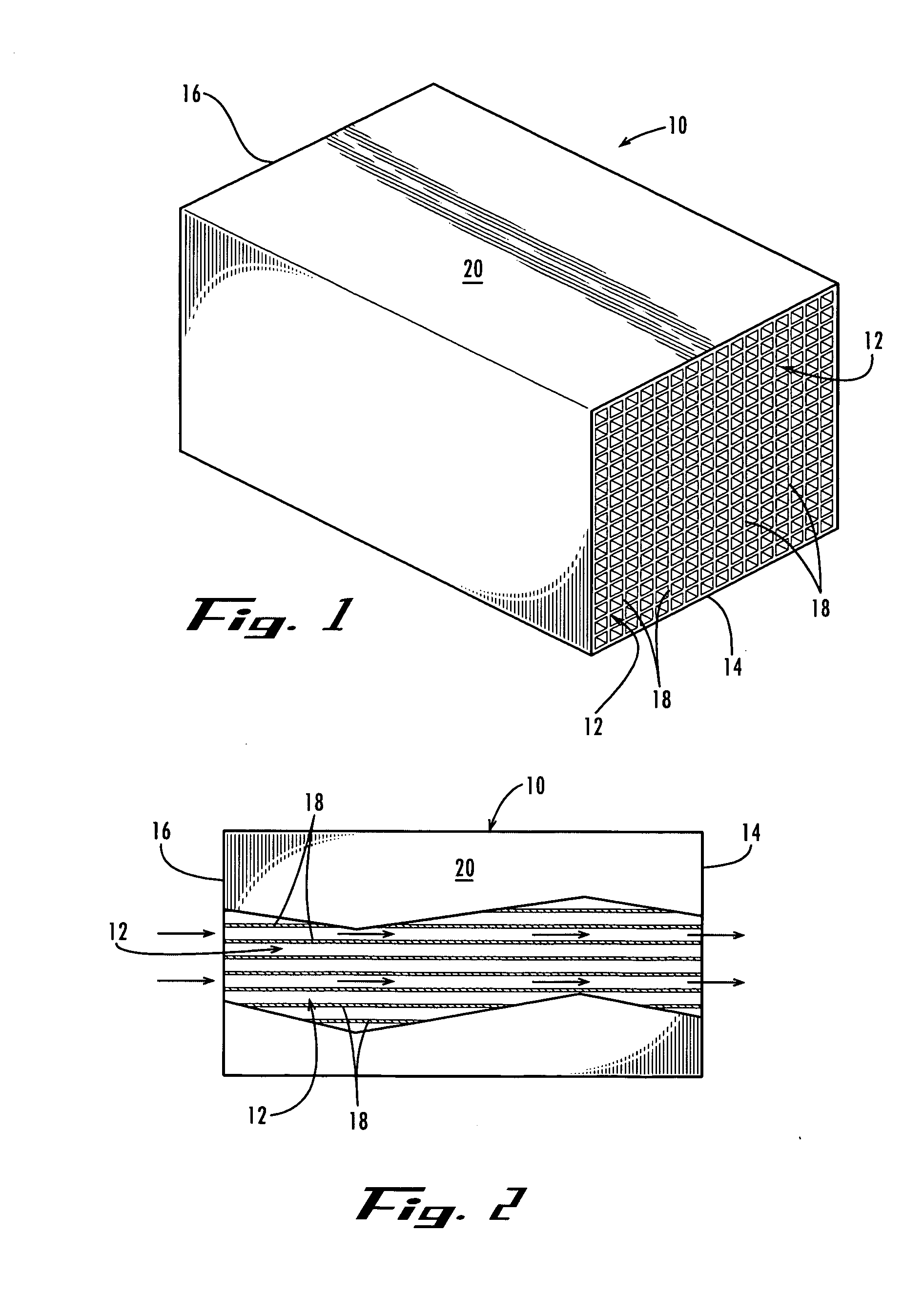
[0076] A finished self-supporting activated carbon monolith made in accordance with U.S. Pat. No. 5,914,294 was placed in the reactor so as to have the sodium carbonate aqueous solution pass evenly through the cells of the monolith as the solution was agitated.

[0077] In another glass container, a solution of palladium chloride was prepared so as to have a palladium metal loading by weight of the carbon monolith of 0.1%. The pH of this solution was adjusted to a pH of 4.0 using sodium bicarbonate. This solution was metered into the reactor.

[0078] After the metering of the palladium solution, the reactor was heated via an...

example 2

[0081] In the same manner of Example 1, a finished self-supporting activated carbon monolith made in accordance with U.S. Pat. No. 5,914,294 was used to prepare a catalyst with a palladium metal loading of 5% by weight of the activated carbon monolith catalyst.

[0082] Ingredients were increased proportionally to the amount of palladium metal used in this Example 2, as compared to Example 1.

example 3

[0083] The activated carbon monolith catalyst of Example 2 was tested for its catalytic activity using nitrobenzene as a test reactant.

[0084] The activated carbon monolith catalyst was placed in the 500 ml glass bottle of a Rocking Parr Bomb. A quantity of 2 ml of pure nitrobenzene was added to the glass bottle along with 50 ml of methanol to act as a solvent. The bottle was inserted into the Rocking Parr Bomb at ambient temperature, which was 22° C. at the time of the test.

[0085] The bottle was pressurized to 60 psig with pure hydrogen. When agitation of the bottle commenced, time and hydrogen pressure in the bottle were recorded. Hydrogen pressure was seen to fall from 60 psig to 43.5 psig in 255 seconds. The temperature of the contents of the bottle were seen to rise from 22° C. to 31° C. in the same time period. These are direct indications of a catalytic reaction occurring with the nitrobenzene and hydrogen due to the presence of the activated carbon monolith catalyst in the ...


PUM

PropertyMeasurementUnit
Fractionaaaaaaaaaa
Fractionaaaaaaaaaa
Fractionaaaaaaaaaa

Abstract

An activated carbon monolith catalyst comprising a finished self-supporting activated carbon monolith having at least one passage therethrough, and comprising a supporting matrix and substantially discontinuous activated carbon particles dispersed throughout the supporting matrix and at least one catalyst precursor on the finished self-supporting activated carbon monolith. A method for making, and a method for use, of such an activated carbon monolith catalyst in catalytic chemical reactions are also disclosed.

Description

FIELD OF THE INVENTION [0001] The present invention relates generally to catalytic structures, methods for making same, and uses thereof. In particular, this invention relates to activated carbon monolith catalysts and methods for making and using them. BACKGROUND OF THE INVENTION [0002] Carbon catalysts play an important role in various chemical processes from industrial to pharmaceutical settings. Carbon catalysts enable chemical reactions to occur much faster, or at lower temperatures, because of changes that they induce in the reactants. Carbon catalysts may lower the energy of the transition state of chemical reactions, thus lowering the activation energy. Therefore, molecules that would not have had the energy to react, or that have such low energies that it is likely that they would take a long time to do so, are able to react in the presence of a carbon catalyst by reducing the energy required for the reaction to occur. Not only do carbon catalysts increase the rate of react...

Claims


Application Information

Patent Timeline
IPC IPC(8): C01B31/08B01J21/18C07C27/00
CPCB01J21/18C01B31/089B01J35/04C01B32/382C07C209/36C07C211/46C07B43/04B01J23/44
Inventor MITCHELL, ROBERT L. SR.MITCHELL, LEE M.KELLER, JOSEPH H.L' AMOREAUX, JACK H.
Owner APPL TECH LLP
Why Eureka
Try Eureka