

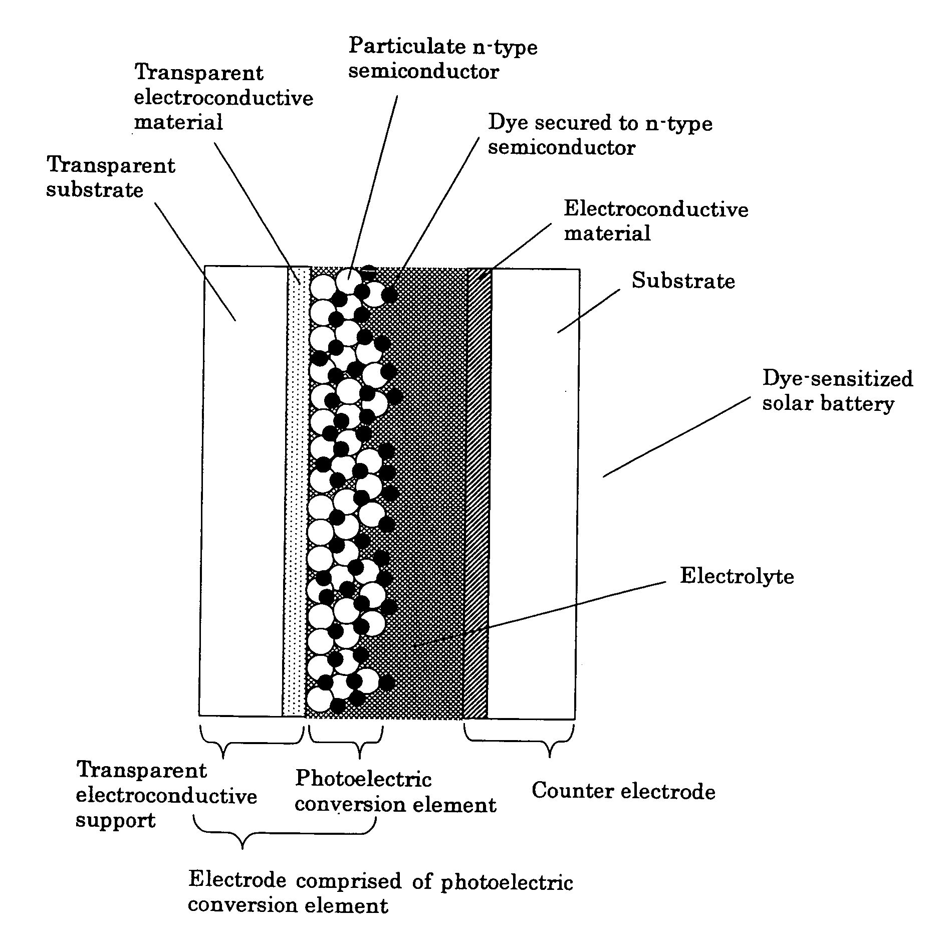
Photoelectric conversion element
a conversion element and photoelectric technology, applied in the field of photoelectric conversion elements, can solve the problems of reducing the amount of fossil fuel available, theoretical limit of energy conversion efficiency, and reducing the efficiency of fossil fuel conversion, so as to achieve excellent photoelectric conversion properties and high energy conversion efficiency. , the effect of high efficiency in solar energy conversion
- Summary
- Abstract
- Description
- Claims
- Application Information
AI Technical Summary
Benefits of technology
Problems solved by technology
Method used
Image

Examples
example 1
(1) Synthesis of a Composite Dye
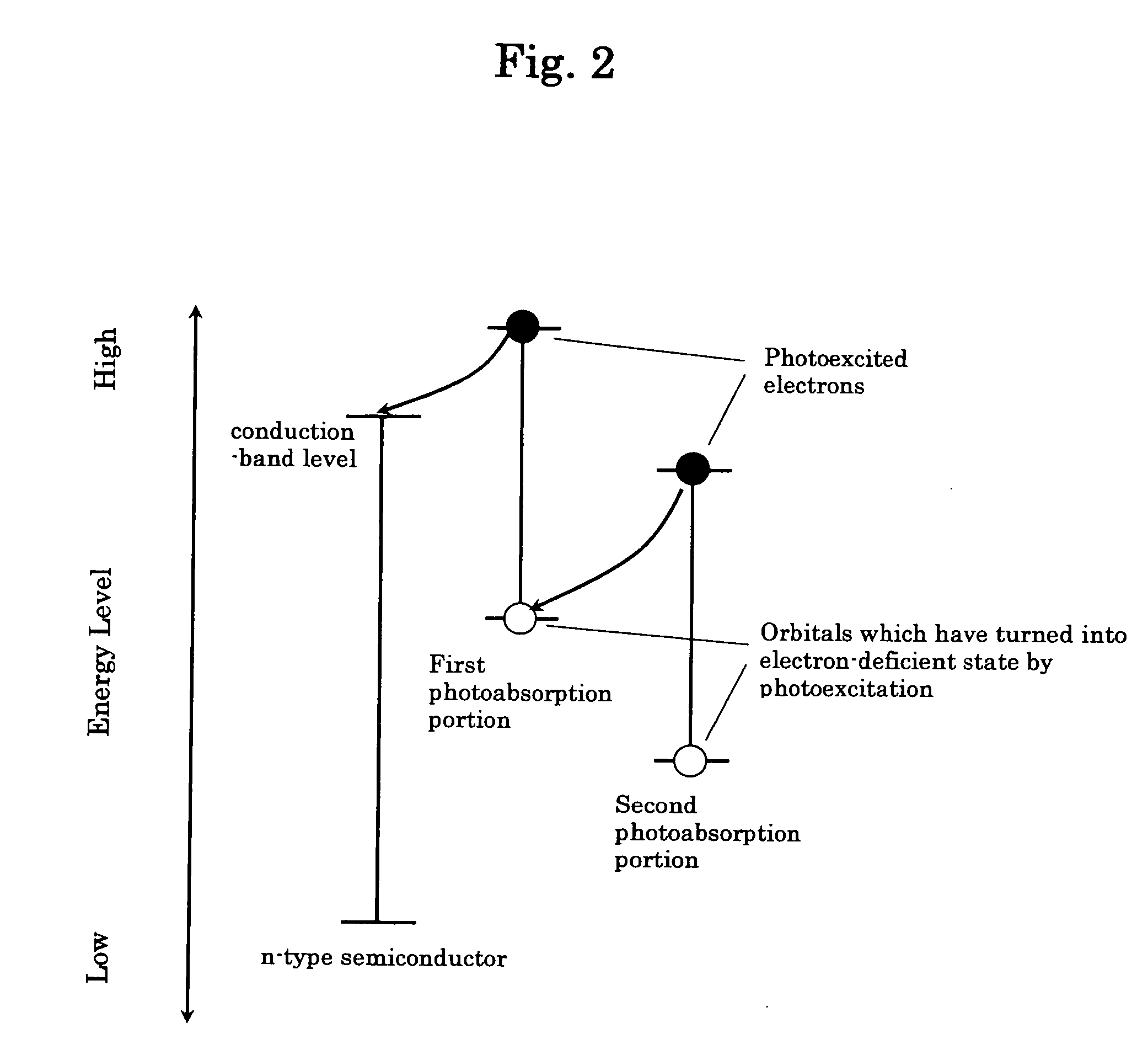
(Synthesis of Component Dye Precursor A (Component Dye A) Corresponding to the First Photoabsorption Portion)
[0229] 0.523 g of ruthenium chloride n-hydrate (reagent; manufactured and sold by Wako Pure Chemical Industries Ltd., Japan) and 50 ml of dimethylformamide were charged into a three-necked flask, followed by stirring in an atmosphere of nitrogen at room temperature for 15 minutes, to thereby obtain a mixture. To the obtained mixture were added 50 ml of dimethylformamide and 0.952 g of 4,4′-dicarboxy-2,2′-bipyridine (reagent; manufactured and sold by Tokyo Kasei Kogyo Co., Ltd., Japan). Then, the resultant mixture was refluxed under heating in an atmosphere of nitrogen for 3 hours under conditions wherein light was shielded, thereby obtaining a mixture. The obtained mixture was allowed to cool to room temperature, followed by a filtration using a filter paper (pore diameter: 5 μm) to obtain a filtrate. Subsequently, the obtained filtrate was...
example 2
(1) Synthesis of a Component Dye
(Synthesis of a Bridging Ligand)
[0243] 1 g of 1,10-phenanthroline-5,6-dione (reagent; manufactured and sold by Sigma-Aldrich Co., U.S.A.) and 0.691 g of dithioxamide (reagent; manufactured and sold by Tokyo Kasei Kogyo Co., Ltd., Japan) were added to 40 ml of ethanol, and the resultant mixture was refluxed under heating in an atmosphere of air for 13 hours. The resultant reaction mixture was allowed to cool to room temperature, and subjected to a suction filtration using a filter paper (pore diameter: 1 μm), thereby obtaining powders. For removing substances remaining unreacted in the obtained powders, the powders were washed with 100 ml of chloroform at room temperature while stirring, followed by a suction filtration using a filter paper (pore diameter: 1 μm), thereby obtaining 0.759 g of 5,6-dihydroxy-1,10-phenanthroline in the form of powders.
(Synthesis of Multinuclear Complex Precursor C (Bonding of a Bridging Ligand to the First Photoabsor...
example 3
(1) Production of a Photoelectric Conversion Element
[0250] An n-type semiconductor dispersion was prepared in substantially the same manner as in Example 1. The prepared dispersion was applied to the electroconductive side-surface of a transparent electroconductive glass (manufactured and sold by Nippon Sheet Glass Co., Ltd., Japan) in which an FTO layer (2.5 cm×5 cm) was provided on a glass substrate, wherein the application of the dispersion was performed in substantially the same manner as in Example 1, except that the wire diameter of the wire bar was changed to 1.0 m / m. Subsequently, the resultant was subjected to drying and sintering in substantially the same manner as in Example 1, followed by adsorption of multinuclear complex Y in substantially the same manner as in Example 2, to thereby obtain a photoelectric conversion electrode (photoelectric conversion element).
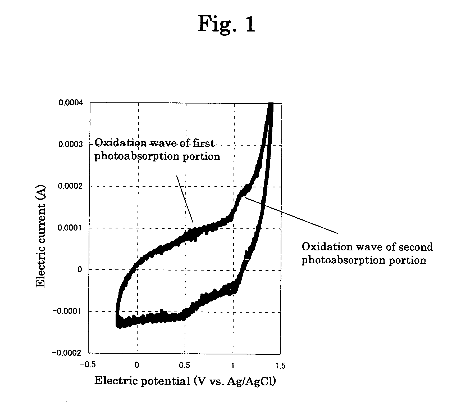
(2) Preparation of an Electrolytic Solution and Photoelectrochemical Measurement
[0251] Tetra-n-butylammon...
PUM
| Property | Measurement | Unit |
|---|---|---|
| particle size | aaaaa | aaaaa |
| particle size | aaaaa | aaaaa |
| particle size | aaaaa | aaaaa |
Abstract
Description
Claims
Application Information