Constitution of the dispersant in the preparation of the electrode active material slurry and the use of the dispersant

Active Publication Date: 2006-11-16
LG ENERGY SOLUTION LTD
View PDF10 Cites 22 Cited by
  • Summary
  • Abstract
  • Description
  • Claims
  • Application Information

AI Technical Summary

Benefits of technology

[0046] When the dispersant according to the present invention is added to the solution of electrode slurry in a small amount, it is possible to improve the dispersibility of the electrode active material by the dispersant and to increase the ratio of solid contents under the same viscosity.
[0047] Additionally,

Problems solved by technology

However, when polyvinylidene fluoride (PVdF) is used as a binder, the interfacial adhesion between a collector and an electrode active material and the close adhesion among the electrode active material molecules is low, and thus the electrode active material pressed and adhered to the collector may be separated and removed from the collector, when a coated electrode is cut to conform to a desired product size, e.g., by slitting, thereby causing the decrease of a nominal voltage or the irregularity of a cell capacity.
Additionally, repeated charge/discharge cycles of a cell may cause the separation and removal of an electrode active material by the shrink and expansion of an electrode.
Accordingly, as charge/discharge cycles are repeated, the removal of the electrode active material from a collector is accelerated, thereby causing the decrease of a cell capacity.
Moreover, a high-voltage state such as overcharge, or a temperature increase resulting from the high-voltage state may cause the decomposition of polyvinylidene fluoride (PVdF) to generate hydrogen fluoride, and thus generated hydrogen fluoride may cause a side reaction with the active material on the surface of the collector or a trace amount of metal

Method used


Image

  • Constitution of the dispersant in the preparation of the electrode active material slurry and the use of the dispersant
  • Constitution of the dispersant in the preparation of the electrode active material slurry and the use of the dispersant
  • Constitution of the dispersant in the preparation of the electrode active material slurry and the use of the dispersant

Examples


Example

EXAMPLE 1

[0065] First, CMC powder (0.26 g; about 1 wt %) used as a thickener for the solution of electrode active material slurry was dissolved in 12.5 g of distilled water at 50° C. to prepare CMC solution. Next, 25 g (about 97 wt %) of graphite powder used as an electrode active material was introduced into a mortar, the CMC solution prepared in advance was poured gradually, and then stirred with a pestle for about 10 minutes. After completion of stirring, 0.51 g (about 1.9 wt %) of SBR solution used as a binder was introduced into the mortar and stirred for additional 5 minutes. Finally, 0.026 g (about 0.1 wt %) of PEO-PMMA copolymer (available from Unichema in the name of Hypermer) used as a dispersant was added and stirred, while adding 43.5 g of distilled water gradually. And then, the solid content of the electrode active material slurry was adjusted to 43 wt %.

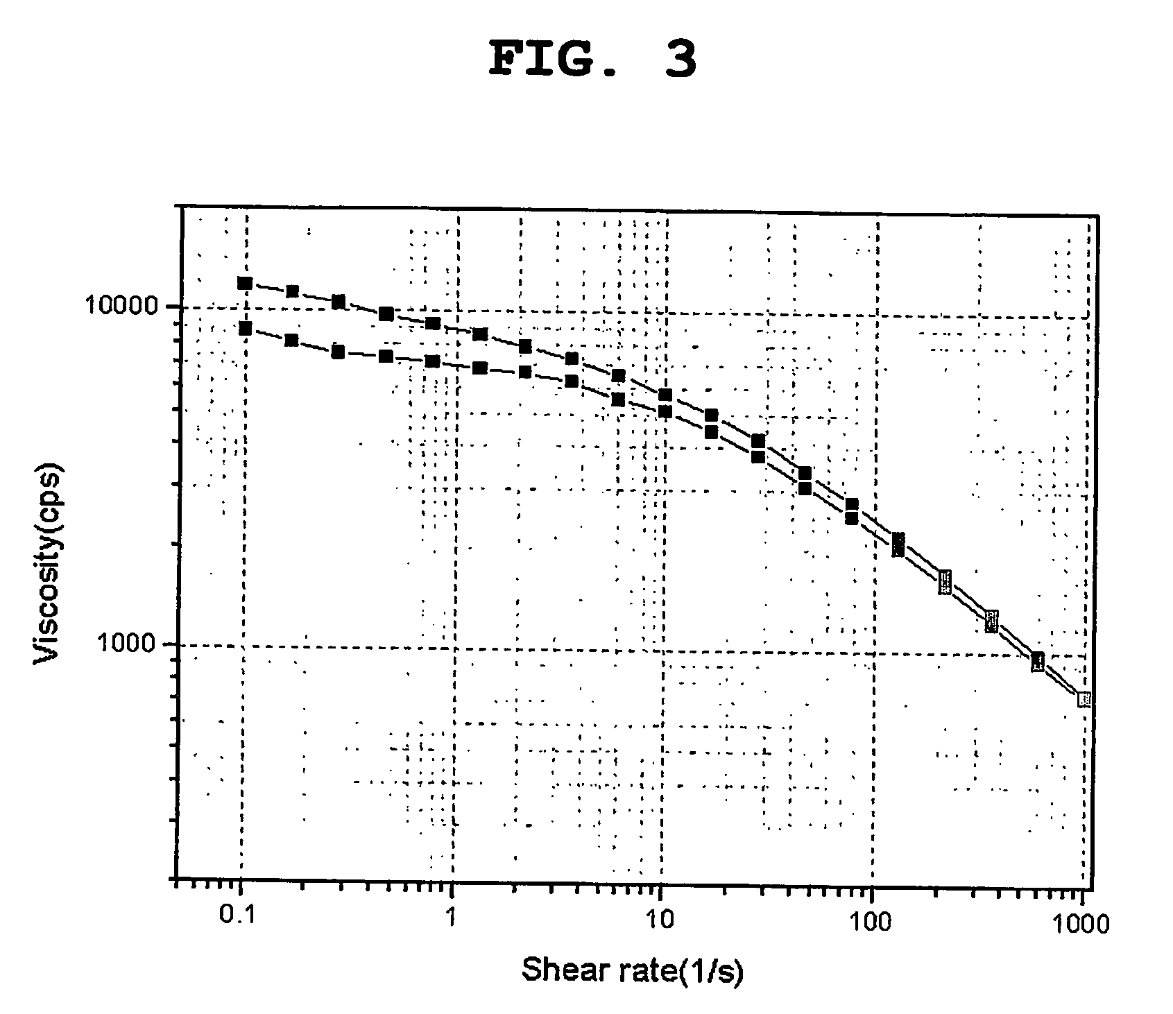
[0066] The viscosity change for the electrode active material slurry prepared as the above was measured by using T...

Example

COMPARATIVE EXAMPLE 1

[0067] Electrode slurry was prepared as described in Example 1, except that the dispersant was not added. The viscosity was measured under the same range of shear rates at 30° C. The results are shown in FIG. 4.

[0068] [Analysis for the Results]

[0069] As shown in FIG. 3 showing the viscosity of Example 1, the graph takes a form in which a viscosity decreases substantially with the same slope, as a shear rate increases. Also, substantially identical viscosity profiles are shown both in the case of increasing the shear rate and in the case of decreasing the shear rate. As can be seen from the foregoing, there was no change in the viscosity of the electrode slurry under the same shear rate.

[0070] However, as shown in FIG. 4, in the case of the anode active material slurry of Comparative Example 1 without using a dispersant, the graph takes a form in which a viscosity has a maximum under a shear rate of 10 (l / s) and decreases again, as a shear rate increases. On t...

Example

COMPARATIVE EXAMPLE 2

[0071] Electrode slurry was prepared as described in Example 1, except that the amount of CMC used as a thickener is increased by 2 wt %, i.e., from 1 wt % to 3 wt % and PEO-PMMA copolymer used as a dispersant was not added. The viscosity was measured under the same range of shear rates. The results are shown in FIG. 5.

[0072] When the amount of CMC was increased from 1 wt % to 3 wt % without adding a dispersant, a viscosity profile similar to that of Example 1 was shown, and thus it seems that the electrode slurry was well dispersed.

[0073] [Experiment on Cell Performance]

[0074] Each of Anode slurries obtained from Example 1 and Comparative Example 2 was applied and coated on a copper foil to form an anode. LiCoO2 as a cathode active material, PE / PP / PE as a separator and EC / PC / DEC, in which LiPF6 was dissolved, as an electrolyte solution were used to manufacture a can-type lithium secondary cell. An experiment for measuring a cell capacity vs. a charge / dischar...


PUM


Abstract

Disclosed are anode active material slurry for a lithium secondary cell having improved dispersibility of an anode active material and a conductive agent, and a lithium secondary cell comprising the same. Particularly, the present invention is characterized by adding a dispersant comprising a polymer backbone capable of surface-adsorption and a side-chain having non-ionic surfactant properties in a small amount, to the anode active material slurry comprising a carbon-based anode active material that is capable of lithium ion intercalation/deintercalation, a conductive agent, a binder comprising a styrene-butadiene-based polymer resin, a thickener comprising a cellulose-based or an acrylate-based resin, and water.

Description

TECHNICAL FIELD [0001] The present invention relates to anode active material slurry having improved dispersibility of an anode active material and a conductive agent, and a lithium secondary cell comprising the same. BACKGROUND ART [0002] In general, a secondary cell using non-aqueous electrolyte solution comprises an anode, a cathode, and a non-aqueous electrolyte layer. In order to form a cathode, cathode slurry comprising a lithium-transition metal oxide as a cathode active material, polyvinylidene fluoride (PVdF) as a binder and N-methyl-2-pyrrolidone (NMP) as a solvent is prepared, the cathode slurry is coated on a collector made of a metal foil, and then drying, pressing and molding steps are performed. In order to form an anode, the same method as described above is performed, except that anode slurry comprising carbon or carbon composite capable of lithium ion intercalation / deintercalation as an anode active material, polyvinylidene fluoride (PVdF) as a binder and N-methyl-...

Claims


Application Information

Patent Timeline
IPC IPC(8): H01M4/62H01M4/58H01M4/60H01M4/02H01M4/133H01M4/1393H01M10/05
CPCH01M4/133H01M4/1393H01M4/587H01M4/62Y02E60/122H01M4/622H01M4/624H01M10/0525H01M2004/027H01M4/621Y02E60/10H01M4/60
Inventor KIM, SEOK KOOKU, CHA HUNAHN, SOON HO
Owner LG ENERGY SOLUTION LTD
Why Eureka
Try Eureka