Degradable medical device

a medical device and degradable technology, applied in the field of medical devices, can solve the problems of only needing stent support, invasive retrieval of stents, and inconvenient use, and achieve the effect of reducing the corrosion of the underlying metal structure, and reducing the risk of infection

Inactive Publication Date: 2006-11-30
KLEINE KLAUS +1
View PDF98 Cites 96 Cited by
  • Summary
  • Abstract
  • Description
  • Claims
  • Application Information

AI Technical Summary

Benefits of technology

[0010] The degree of porosity that is imparted to the metal or combination of metals selected for use in the construction of the medical device is an essential element for the practice of the present invention. The porosity has a substantial effect on the rate of corrosion to the extent that the ratio of corrosion rate increase to surface area increase has been found to vary from 0.3 to 1.0 depending on the type of material and the environment to which it is exposed. The morphology of the microcellular porous metal, including the cell size and porosity of the metal, can be controlled so that the cell sizes can be made very uniform, and can be controlled precisely by the manipulation of various parameters during the formation process. The desired porosity is achievable by a variety of techniques including, but not limited to sintering, foaming, extrusion, thixomolding, semi-s...

Problems solved by technology

Various medical devices are routinely implanted in a body lumen such as a blood vessel, wherein a permanent presence is not required and wherein an extended presence may actually be counterproductive.
It has however been found that the support that is provided by a stent is only required for a limited period of time, perhaps on the order of months, as the part of the vessel affected by stenosis would thereafter typically remain open even without any further support.
The continued presence of some scent structures would then only serve as a permanent irritation of the tissue surrounding the stent, as the stent's rigidity could preclude it from performing the flexions caused by the heartbeat.
An additional complication arises in pediatric applications because the stent comprises a fixed obstruction at the implant...

Method used


Image

  • Degradable medical device
  • Degradable medical device

Examples


Embodiment Construction

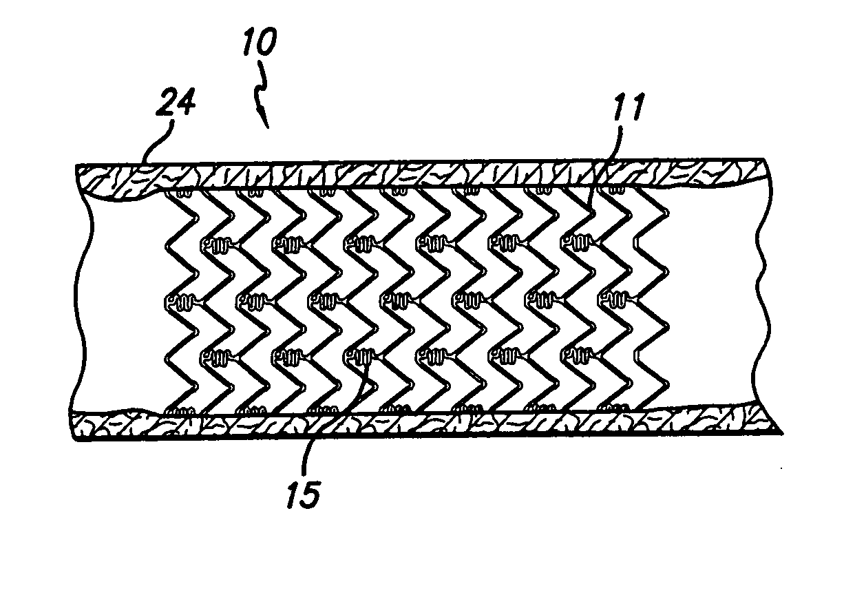
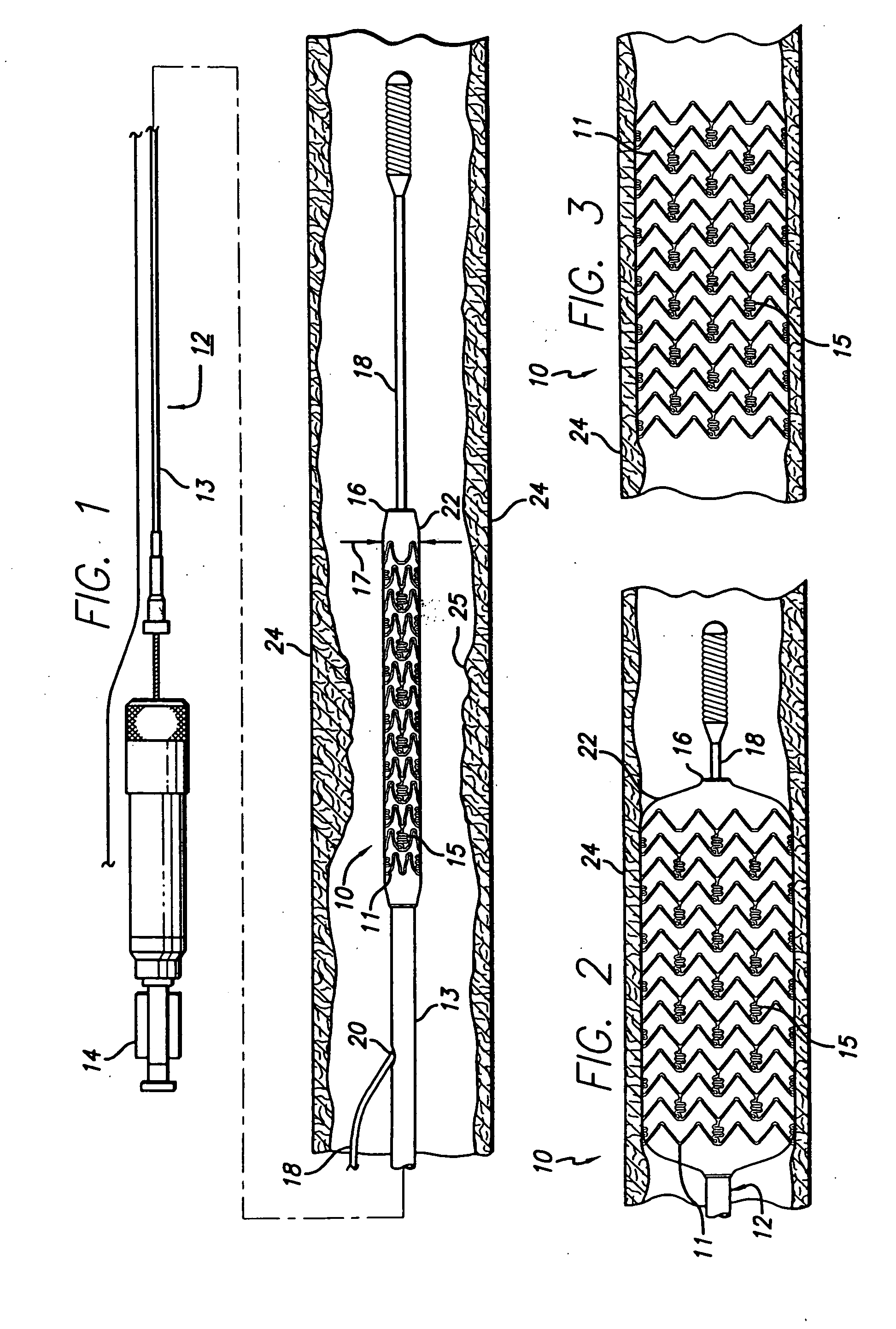
[0017]FIG. 1 generally depicts a corrodible metal stent 10, incorporating features of the invention, mounted on a catheter assembly 12 which is used to deliver the stent and implant it in a body lumen, such as a coronary artery, carotid artery, peripheral artery, or other vessel or lumen within the body. The stent generally comprises a plurality of radially expandable cylindrical rings 11 disposed generally coaxially and interconnected by undulating links 15 disposed between adjacent cylindrical elements. The catheter assembly includes a catheter shaft 13 which has a proximal end 14 and a distal end 16. The catheter assembly is configured to advance through the patient's vascular system by advancing over a guide wire by any of the well known methods of an over the wire system (not shown) or a well known rapid exchange catheter system, such as the one shown in FIG. 1.

[0018] Catheter assembly 12 as depicted in FIG. 1 is of the well known rapid exchange type which includes an RX port ...


PUM

PropertyMeasurementUnit
Electric potential / voltageaaaaaaaaaa
Porosityaaaaaaaaaa
Forceaaaaaaaaaa

Abstract

An implantable medical device is provided that degrades upon contact with body fluids so as to limit its residence time within the body. The device is formed of a porous corrodible metal to simultaneously provide high strength and an accelerated corrosion rate. The corrosion rate of a device formed of metal subject to self-dissolution or of a combination of metals subject to galvanic corrosion is accelerated by its porous structure. Coating the corrodible metallic device with a degradable polymer serves to delay the onset of corrosion of the underlying metallic structure.

Description

CROSS-REFERENCES TO RELATED APPLICATIONS [0001] This is a continuation-in-part of currently pending U.S. patent application Ser. No. 10 / 283,951, filed Oct. 30, 2002, entitled POROUS METAL FOR DRUG LOADED STENTS.BACKGROUND OF THE INVENTION [0002] The present invention relates generally to medical devices which are adapted for implantation into a patient's body lumen and which are intended to degrade after implantation to eventually become absorbed and / or eliminated by the body. More particularly, the invention is applicable to a stent for deployment in a blood vessel in which its presence is only temporarily required. [0003] Various medical devices are routinely implanted in a body lumen such as a blood vessel, wherein a permanent presence is not required and wherein an extended presence may actually be counterproductive. For example, stents are particularly useful in the treatment and repair of blood vessels after a stenosis has been compressed by percutaneous transluminal coronary ...

Claims


Application Information

Patent Timeline
IPC IPC(8): A61F2/06A61F2/00
CPCA61F2/91A61F2/915A61F2002/91533A61F2002/91575A61F2250/0068A61F2230/0054A61L31/10A61L31/146A61L31/148A61L31/16A61L2300/606A61L31/022
Inventor KLEINE, KLAUSKRAMER-BROWN, PAMELA
Owner KLEINE KLAUS
Why Eureka
Try Eureka