Display comprising liquid crystal droplets in a hydrophobic binder

a technology of hydrophobic binders and liquid crystal droplets, which is applied in the direction of thin material processing, material nanotechnology, instruments, etc., can solve the problems of loss of performance, change in reflected color, ultraviolet radiation harmful to liquid crystals, etc., and achieve low switching voltage, high contrast, and low cost

Active Publication Date: 2006-12-21
IRIS OPTRONICS CO LTD
View PDF13 Cites 9 Cited by
  • Summary
  • Abstract
  • Description
  • Claims
  • Application Information

AI Technical Summary

Benefits of technology

[0018] The present invention includes several advantages, not all of which are incorporated in a single embodiment. A display according to the present invention would be low cost and require low switching voltage. In the case of a cholesteric or chiral nematic liquid crystal display, the resulting display is expected to have reflectance closer to the theoretical limit of 50% and higher contrast. The use of a hydrophobic bi

Problems solved by technology

While the emulsion methods are straightforward to implement, droplet size distributions tend to be broad resulting in a loss in performance.
Although phase separation methods produce dispersed droplets having more uniform size distributions, there are numerous problems with this approach.
Furthermore, it is also known that ultraviolet radiation is harmful to liquid crystals.
Specifically, exposure to ultraviolet radiation can lead to decomposition of the chiral dopant in a cholesteric liquid crystal mixture, resulting in a change in the reflected color.
The use of organic solvents may also be objectionable in certain manufacturing environments.
The latter has a significant effect on the overall cost of the display.
The device described by U.S. Pat. No. 6,423,368 and U.S. Pat No. 6,704,073 suffers from drawbacks because of the structure of the coated layer.
Furthermore, the process of coating a heated emulsion of the liquid crystal in a gelatin binder onto a substrate with a conductive layer and subsequently lowering the temperature of the coating to change the state of the coated layer from a free flowing liquid to a gel state (referred to as a sol-gel transition) prior to drying the coating results in an extremely uneven distribution of droplets of liquid crystal.
The uneven distribution of droplets results in a decrease in contrast and an increase in switching voltage.
However, no attempt is made to control the thickness or the distribution of droplets in the coated layer resulting in less than optimum performance.
While the method provides displays with an improvement in brightness and contrast, it still falls short of optimum performance because the gelatin binder is made to undergo a sol-gel transition prior to drying of the coating resulting in an uneven structure.
Both features result in a low switching voltage.
However, there are numerous problems with this approach.
When a droplet at the tip of the capillary grows to reach critical size, viscous drag exceeds surface tension and breakoff occurs, producing highly monodisperse emulsions.
Clearly, this method of creating one droplet at a time is not suitable for large scale manufacture.
Secon

Method used


Image

  • Display comprising liquid crystal droplets in a hydrophobic binder
  • Display comprising liquid crystal droplets in a hydrophobic binder

Examples


example 1 (

INVENTION)

[0119] A chiral nematic composition with center wavelength of reflection (CWR) of 590 nm was prepared by adding the appropriate amount of a high twist chiral dopant to the nematic host mixture BL087 obtained from Merck, Darmstadt, Germany.

[0120] A dispersion of the cholesteric liquid crystal composition with CWR at 590 nm was prepared as follows. To 502 grams of distilled water was added 7.5 grams of Ludox TM colloidal silica suspension and 15.5 grams of a 10% w / w aqueous solution of a copolymer of methylaminoethanol and adipic acid. To this was added 225 grams of the cholesteric liquid crystal composition. The mixture was stirred using a Silverson mixer at 5000 rpm. It was then passed through a microfluidizer at 3000 psi. Finally, the resulting dispersion was passed through a 23 μm filter. The droplet size distribution in the dispersion was measured using a Coulter Counter. It was found that the mean size was 9.5 microns and the coefficient of variation (cv) was 0.14.

[0...

example 2 (

CONTROL)

[0124] A chiral nematic composition with center wavelength of reflection (CWR) of 590 nm was prepared by adding the appropriate amount of a high twist chiral dopant to the nematic host mixture BL087 obtained from Merck, Darmstadt, Germany.

[0125] A dispersion of the cholesteric liquid crystal composition with CWR at 590 nm was prepared as follows. To 502 grams of distilled water was added 7.5 grams of Ludox TM colloidal silica suspension and 15.5 grams of a 10% w / w aqueous solution of a copolymer of methylaminoethanol and adipic acid. To this was added 225 grams of the cholesteric liquid crystal composition. The mixture was stirred using a Silverson mixer at 5000 rpm. It was then passed through a microfluidizer at 3000 psi. Finally, the resulting dispersion was passed through a 23 μm filter. The droplet size distribution in the dispersion was measured using a Coulter Counter. It was found that the mean size was 9.5 microns and the coefficient of variation (cv) was 0.14.

[012...

example 3 (

CONTROL)

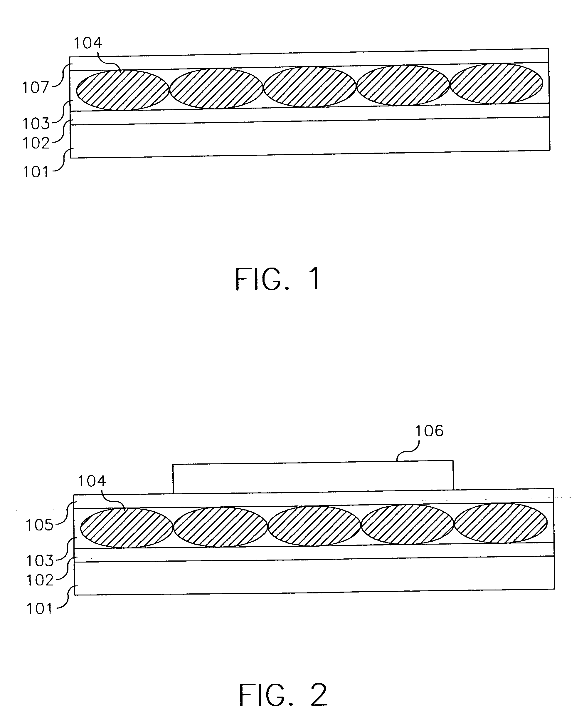
[0129] Example 3 demonstrates the results achieved when coating or printing a conductive layer onto a liquid crystal layer, with a barrier layer, resulting in increased thickness, to protect the liquid crystal layer from the carrier solvent for the conductive layer.

[0130] A chiral nematic composition with center wavelength of reflection (CWR) of 590 nm was prepared by adding the appropriate amount of a high twist chiral dopant to the nematic host mixture BL087 obtained from Merck, Darmstadt, Germany.

[0131] A dispersion of the cholesteric liquid crystal composition with CWR at 590 nm was prepared as follows. To 502 grams of distilled water was added 7.5 grams of Ludox TM colloidal silica suspension and 15.5 grams of a 10% w / w aqueous solution of a copolymer of methylaminoethanol and adipic acid. To this was added 225 grams of the cholesteric liquid crystal composition. The mixture was stirred using a Silverson mixer at 5000 rpm. It was then passed through a microfluidizer a...


PUM

PropertyMeasurementUnit
Lengthaaaaaaaaaa
Surface roughnessaaaaaaaaaa
Electrical conductivityaaaaaaaaaa

Abstract

The present invention relates to a display comprising at least one substrate and at least one electronically modulated imaging layer and at least one electrically conductive layer, wherein the electronically modulated imaging layer comprises a self-assembled, close-packed, ordered monolayer of domains of electrically modulated material in a water insoluble, hydrophobic polymer matrix and the at least one electrically conductive layer comprises electronically conductive polymer and a conductivity enhancing agent.

Description

FIELD OF THE INVENTION [0001] The present invention relates to the use of hydrophobic binders in electronic displays BACKGROUND OF THE INVENTION [0002] There is significant interest in low cost flexible electronic displays. Typically, such displays comprise a light modulating component embedded in a binder (most commonly polymer) matrix that is coated over a conductive plastic support. Broadly speaking, a light modulating component is a material that changes its optical properties such as its ability to reflect or transmit light in response to an electric field. The light modulating component may be a liquid crystalline material such as a nematic liquid crystal, a chiral nematic or cholesteric liquid crystal or a ferroelectric liquid crystal. The light modulating material may also be a water insoluble liquid containing particles that undergo electrophoresis or motion such as rotation or translation in response to an electric field. Displays comprising a liquid crystalline material i...

Claims


Application Information

Patent Timeline
IPC IPC(8): C09K19/00C09K19/38
CPCB82Y30/00C09K19/544G02F1/1334Y10T428/1005Y10T428/10Y10T428/1036G02F2001/13345C09K2323/02C09K2323/03C09K2323/00G02F1/13345
Inventor CHARI, KRISHNANMAJUMDAR, DEBASIS
Owner IRIS OPTRONICS CO LTD
Why Eureka
Try Eureka