Manganese doped barium titanate thin film compositions, capacitors, and methods of making thereof

a technology of manganese doped barium titanate and composition, applied in the direction of thin/thick film capacitor, fixed capacitor details, fixed capacitors, etc., can solve the problems of low current density, power overshoot, and low leakage current under applied bias

Inactive Publication Date: 2006-12-21
EI DU PONT DE NEMOURS & CO +1
View PDF20 Cites 24 Cited by
  • Summary
  • Abstract
  • Description
  • Claims
  • Application Information

AI Technical Summary

Benefits of technology

[0010] The present invention is directed to a dielectric thin film composition comprising: (1) one or more barium / titanium-containing selected from (a) barium titanate, (b) any composition that can form barium titanate during firing, and (c) mixtures thereof; dissolved in (2) organic medium; and wherein said thin film composition is doped with 0.002 to 0.05 atom percent of a manganese-containing additive.

Problems solved by technology

As semiconductor devices including integrated circuits (IC) operate at higher frequencies, higher data rates and lower voltages, noise in the power and ground (return) lines and supplying sufficient current to accommodate faster circuit switching becomes an increasingly important problem requiring low impedance in the power distribution system.
If the response time of the voltage supply is too slow, the microprocessor will experience a voltage drop or power droop that will exceed the allowable ripple voltage and noise margin and the IC will trigger false gates.
Additionally, as the IC powers up, a slow response time will result in power overshoot.
In this case, large numbers of capacitors requires complex electrical routing which leads to inductance.
The low oxygen partial pressures, however, often result in high leakage currents under applied bias (current densities) in barium titanate based compositions due to reduction of the dielectric material.
In worst case situations, the capacitor may be shorted and dielectric properties cannot be measured.
This may be addressed by a subsequent re-oxidation procedure carried out at lower temperatures in which the dielectric and metal foil is exposed to higher partial pressures of oxygen but this results in oxidation of the base metal foil.
This procedure oxidized the foil and did not necessarily produce optimum capacitor performance, particularly with respect to leakage current density under bias.
It is also not cost effective to re-oxidize the dielectric in a separate step.

Method used


Image

  • Manganese doped barium titanate thin film compositions, capacitors, and methods of making thereof
  • Manganese doped barium titanate thin film compositions, capacitors, and methods of making thereof
  • Manganese doped barium titanate thin film compositions, capacitors, and methods of making thereof

Examples


example 1

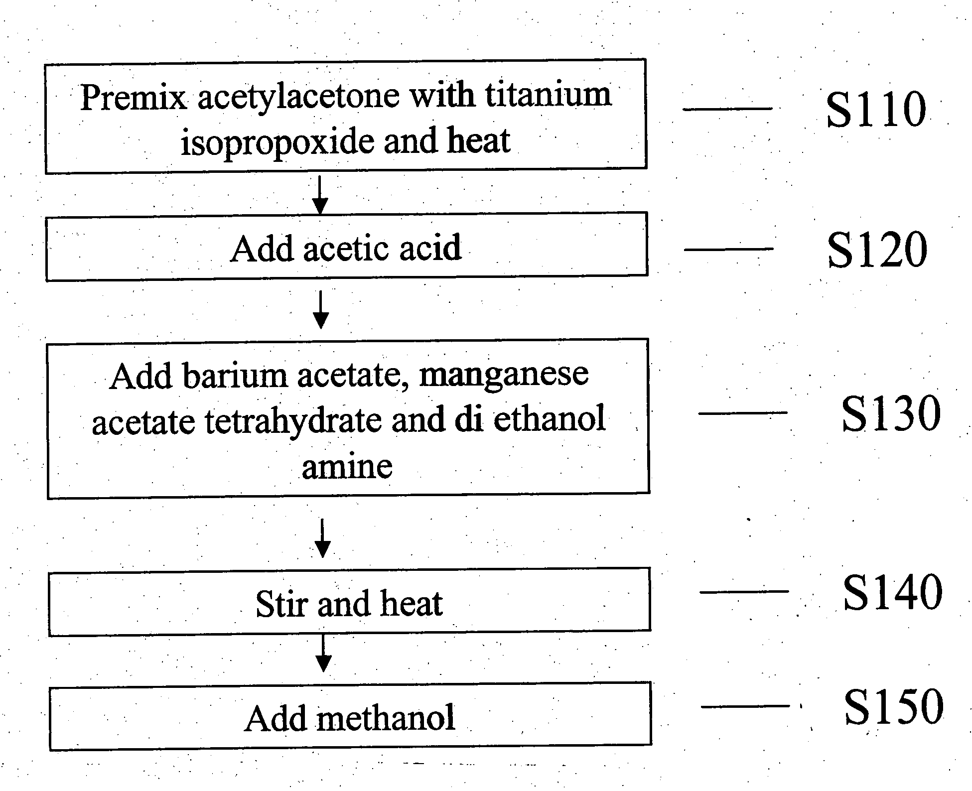
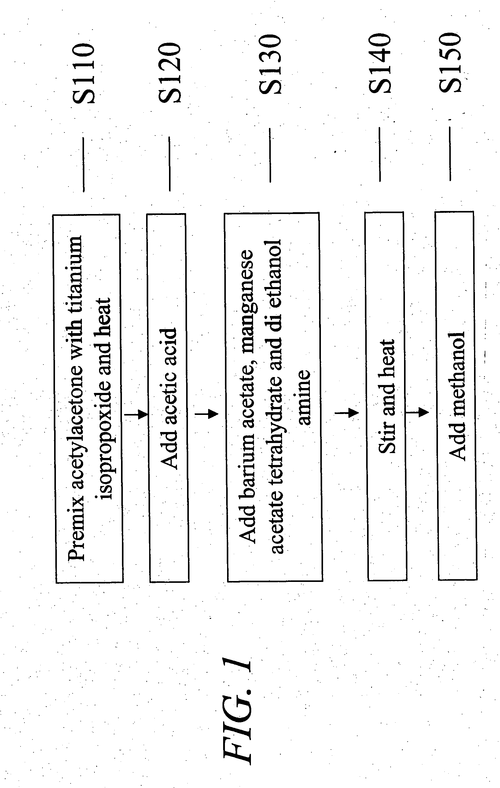
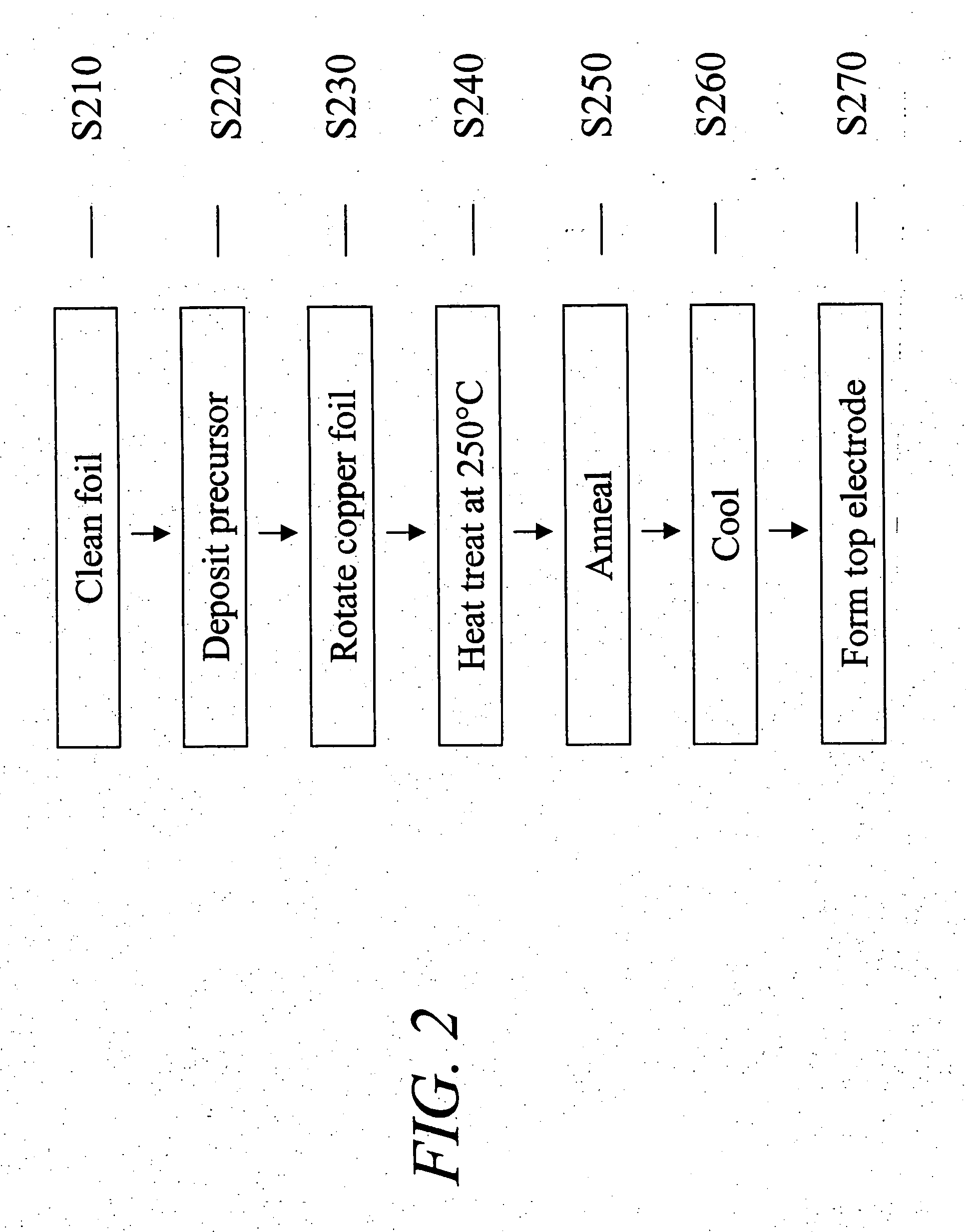
[0050] A thin film un-doped pure barium titanate film was prepared on a copper foil using a precursor as disclosed in U.S. National patent application Ser. No. 10 / 621,796 (U.S. Patent Publication No. 2005-001185). The copper foil was coated with the dielectric precursor composition using the method outlined in FIG. 2. The composition of the dielectric precursor was as given below:

Barium acetate2.6gTitanium isopropoxide2.9mlAcetylacetone2.0mlAcetic acid10.0mlMethanol15ml

[0051] Three spin coats were applied. The coated copper foil was annealed at 900° C. for 30 minutes under a partial pressure of oxygen of approximately 10−11 atmospheres. After annealing, the pure barium titanate was re-oxidized by placing the foil in a vacuum chamber under an atmosphere of approximately 10−5 Torr of oxygen at 550° C. for 30 minutes. This condition was chosen to avoid significant oxidation of the copper foil while still providing oxygen for re-oxidation of the dielectric. After re-oxidation, a top p...

example 2

[0053] A thin film 0.01 atom percent manganese doped barium titanate film was prepared on a copper foil. The copper foil was coated with the dielectric precursor composition using the method outlined in FIG. 2. The composition of the dielectric precursor was as given below:

Barium acetate5.08gTitanium isopropoxide5.68mlAcetylacetone3.86mlAcetic acid21mlMethanol24.26mlManganese acetate0.002gDiethanolamine0.54g

[0054] The only difference in inorganic levels between example 1 and example 2 is the manganese. The diethanolamine is a stress reducing organic material and has no effect on the final inorganic composition. Three spin coats were applied. The coated copper foil was annealed at 900° C. for 30 minutes at a partial pressure of oxygen of approximately 10−11 atmospheres. A top platinum electrode was sputtered on to the dielectric and the electrical characteristics of the capacitor were measured.

[0055] As shown in FIG. 5, the doped barium titanate layer without re-oxidation exhibite...

example 3

[0056] A 0.02 atom percent manganese doped barium titanate thin film was prepared on a copper foil in the similar manner described in EXAMPLE 1 using the precursor solution described below except the coating / pre-baking process was repeated six times. The manganese dopant solution was prepared by dissolving Mn(OAc)2 (0.2 g) in hot acetic acid (29.8 g):

Barium acetate 2.0 gTitanium isopropoxide2.22 gAcetylacetone1.56 gAcetic acid17.0 gDiethanolamine0.21 gManganese dopant solution0.17 g

[0057] The capacitance density and loss tangent for a manganese doped barium titanate layer without re-oxidation are shown in FIG. 7. The capacitance density was approximately 1.4 μF / cm2 at 0 volt and the loss tangent was 2 at 10 volts bias or approximately 1,000,000 times lower leakage current flow versus the re-oxidized undoped barium titanate.


PUM

PropertyMeasurementUnit
temperatureaaaaaaaaaa
partial pressureaaaaaaaaaa
thicknessaaaaaaaaaa

Abstract

The present invention is directed to a dielectric thin film composition comprising: (1) one or more barium/titanium-containing selected from (a) barium titanate, (b) any composition that can form barium titanate during firing, and (c) mixtures thereof; dissolved in (2) organic medium; and wherein said thin film composition is doped with 0.002 to 0.05 atom percent of a manganese-containing additive.

Description

TECHNICAL FIELD [0001] The present invention pertains to thin film capacitors, more particularly to thin film capacitors formed on copper foil that can be embedded in printed wiring boards (PWB) to provide capacitance for decoupling and controlling voltage for integrated circuit die that are mounted on the printed wiring board package. BACKGROUND [0002] As semiconductor devices including integrated circuits (IC) operate at higher frequencies, higher data rates and lower voltages, noise in the power and ground (return) lines and supplying sufficient current to accommodate faster circuit switching becomes an increasingly important problem requiring low impedance in the power distribution system. In order to provide low noise, stable power to the IC, impedance in conventional circuits is reduced by the use of additional surface mount technology (SMT) capacitors interconnected in parallel. The higher operating frequencies (higher IC switching speeds) mean that voltage response times to ...

Claims


Application Information

Patent Timeline
Patent Type & Authority Applications(United States)
IPC IPC(8): C04B35/00
CPCC01G23/006C01P2004/82C01P2006/40H01G4/1227H01G4/33H01L21/31691Y10T29/4913H05K2201/0175H05K2201/0179H05K2201/0355Y10T29/435Y10T29/417H05K1/162Y10T428/31678H01L21/02197H01G4/10H01G4/12H01L21/02337
Inventor BORLAND, WILLIAM J.BURN, IANIHLEFELD, JON FREDRICKMARIA, JON-PAULSUH, SEIGI
Owner EI DU PONT DE NEMOURS & CO
Why Eureka
Try Eureka