

Electroluminescent devices containing benzidine derivatives
a technology of electroluminescent devices and derivatives, which is applied in the direction of discharge tube luminescnet screens, natural mineral layered products, transportation and packaging, etc., can solve the problems of difficult to find suitable hole-transporting materials that afford good operating lifetimes at high temperatures, and their performance limitations have represented a barrier to many desirable applications. , to achieve the effect of improving the operating lifetim
- Summary
- Abstract
- Description
- Claims
- Application Information
AI Technical Summary
Benefits of technology
Problems solved by technology
Method used
Image

Examples
example 1
Synthesis of Cpd-5
[0203]
[0204] Intermediate N,N′-di(tolyl)benzidine (Int-1, eq. 1) was prepared by combining 4,4′-dibromobiphenyl (3.12 g, 10 mmol), p-toluidine (2.14 g, 20 mmol), sodium t-butoxide (2.16 g, 22.5 mmol), tris(dibenzylideneacetone)dipalladium(0) (0.27 g, 0.3 mmol), 1,1′-bis(diphenylphopsphino)ferrocene (0.25 g, 0.45 mmol) and 60 mL of toluene and the mixture was heated to reflux under a nitrogen atmosphere for 18 h. The reaction mixture was cooled to room temperature and filtered. The solid collected was washed with toluene (two 10 mL portions), water (two 10 mL portions), and then ethanol (two 10 mL portions). The solid was dried in vacuo for 2 h to afford 2.75 g of Int-1. Analysis by H1-NMR spectroscopy and mass spectroscopy confirmed the structure of Int-1.
[0205] Cpd-5 (see eq. 2) was prepared by combining Int-1 (2.95 g, 8.1 mmol), Int-2 (2.2 g, 17.8 mmol, prepared by the procedure of J. Pei and co-workers, J. Org. Chem., 67, 4924 (2002)), sodium t-butoxide (1.92 ...
example 2
Measurement of Oxidation Potentials and Glass Transition Temperatures
[0206] A Model CHI660 electrochemical analyzer (CH Instruments, Inc., Austin, Tex.) was employed to carry out the electrochemical measurements. Cyclic voltammetry (CV) and Osteryoung square-wave voltammetry (SWV) were used to characterize the redox properties of the compounds of interest. A glassy carbon (GC) disk electrode (A=0.071 cm2) was used as working electrode. The GC electrode was polished with 0.05 μm alumina slurry, followed by sonication cleaning in Milli-Q deionized water twice and rinsed with acetone in between water cleaning. The electrode was finally cleaned and activated by electrochemical treatment prior to use. A platinum wire served as counter electrode and a saturated calomel electrode (SCE) was used as a quasi-reference electrode to complete a standard 3-electrode electrochemical cell. Ferrocene (Fc) was used as an internal standard (EFc=0.50 vs.SCE in 1:1 acetonitrile / toluene, EFc=0.55 vs. SC...
example 3
Preparation of Devices 1-1 through 1-7
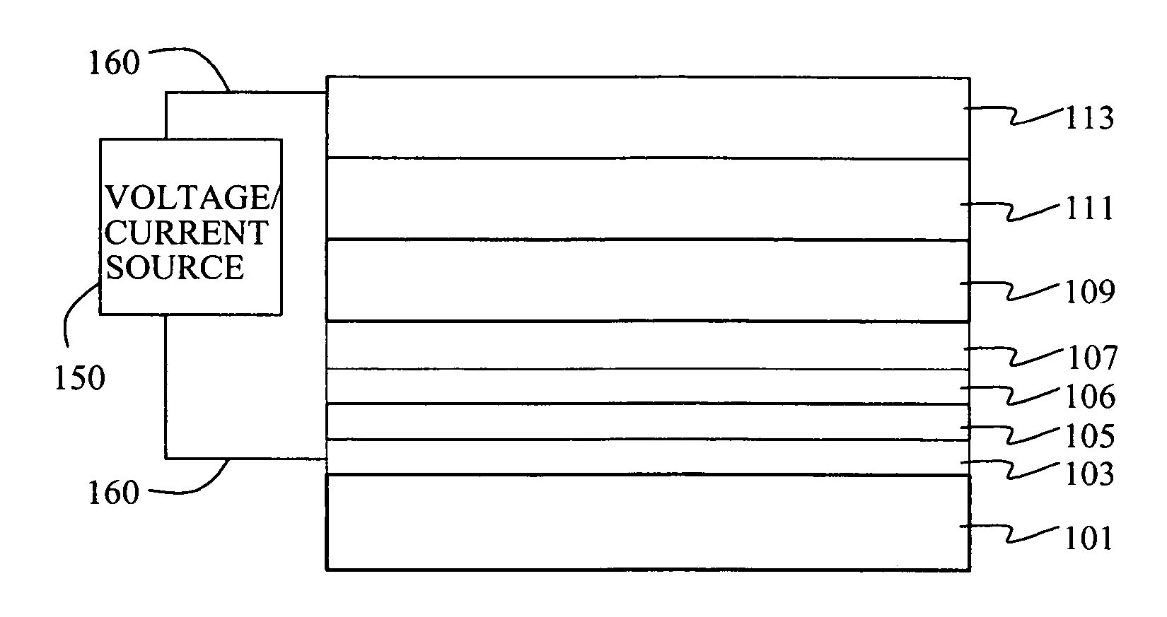
[0210] A series of EL devices (1-1 through 1-7) were constructed in the following manner. [0211] 1. A glass substrate coated with an 85 nm layer of indium-tin oxide (ITO), as the anode, was sequentially ultrasonicated in a commercial detergent, rinsed in deionized water, degreased in toluene vapor and exposed to oxygen plasma for about 1 min. [0212] 2. Over the ITO, for some devices (see Table 2a) was deposited a 1 nm fluorocarbon (CFx) hole-injecting layer (HIL) by plasma-assisted deposition of CHF3 as described in U.S. Pat. No. 6,208,075. [0213] 3. Next a layer (L2, when present, see Table 2a) corresponding to Cpd-5 was deposited to a thickness shown in Table 2a. [0214] 4. Next a layer (L1) of HTM-3 or Cpd-5 (see Table 2a) was vacuum-deposited corresponding to a thickness shown in Table 2a. [0215] 5. A 40 nm light-emitting layer (LEL) corresponding to 99.25% 9,10-di(2-naphthyl) anthracene and 0.75% of dopant L55 was then deposited. [0216] 6. ...
PUM
| Property | Measurement | Unit |
|---|---|---|
| Temperature | aaaaa | aaaaa |
| Electric potential / voltage | aaaaa | aaaaa |
| Glass transition temperature | aaaaa | aaaaa |
Abstract
Description
Claims
Application Information