Ceramic membranes with integral seals and support, and electrochemical cells and electrochemical cell stacks including the same

a ceramic membrane and seal technology, applied in the field of ceramic membranes with integral seals and support, and electrochemical cells and electrochemical cell stacks including the same, can solve the problems of difficult scaling to large power stacks, low volumetric or gravimetric power density of conventional tubular cells, and difficult processing of cathode-supported cells. , to achieve the effect of avoiding diffusion limitation of performance, low ohmic contribution of the electrolyte layer, and high mechanical strength

Inactive Publication Date: 2007-03-08
NEXCERIS INNOVATION HLDG LLC
View PDF1 Cites 29 Cited by
  • Summary
  • Abstract
  • Description
  • Claims
  • Application Information

AI Technical Summary

Benefits of technology

[0015] The present invention provides a mechanically robust supported ceramic membrane structure. This structure provides the advantages of both electrolyte-supported cells (a dense sealing perimeter, high mechanical strength, and thin electrode layers that avoid diffusion limitation of performance) and electrode-supported cells (low ohmic contribution of the electrolyte layer and the potential for low temperature operation) without the drawbacks of these conventional cells. The structure is useful in the fabrication of electrochemical cells; when appropriate electrode materials are selected, the cell may be used as a fuel cell, oxygen separator, or other electrochemical device.

Problems solved by technology

Conventional tubular cells typically suffer from low volumetric or gravimetric power density because large tubes do not pack well and have a low surface area to volume ratio.
However, microtubular cells require complex manifolding and electrical interconnection schemes, which makes scaling to large power stacks difficult.
However, processing of cathode-supported cells is difficult because the co-firing of most cathode materials in contact with an electrolyte produces insulating intermediate compounds.
However, anode-supported cells are not without drawbacks.
When conventional nickel oxide / yttrium-stabilized zirconia (NiO / YSZ) composites are used as support materials, the reduction of NiO to nickel metal creates stress in the electrolyte layer, which may cause considerable deformation during this reduction process.
Operating planar anode-supported cells at high power density and high fuel utilization also is difficult; the thick porous layer prevents rapid diffusion of steam away from the electrolyte and results in increased cell area-specific resistance (ASR) at high current density.
Because only a thin layer of anode ink is affected by the reduction process, this process generally has little impact on cell mechanical stability.
The higher operating temperature of the electrolyte-supported cells can be a drawback, particularly for developers wishing to use metallic interconnect materials.
In spite of more than thirty years of continuous research in the area of SOFCs, these systems remain far from commercialization.
Until SOFC cells are developed that address the shortcomings of existing cell structures, it will be difficult for SOFCs to overcome the commercialization barriers and compete with conventional energy production routes.

Method used


Image

  • Ceramic membranes with integral seals and support, and electrochemical cells and electrochemical cell stacks including the same
  • Ceramic membranes with integral seals and support, and electrochemical cells and electrochemical cell stacks including the same
  • Ceramic membranes with integral seals and support, and electrochemical cells and electrochemical cell stacks including the same

Examples


example 1

Preparation of Membrane Structure I

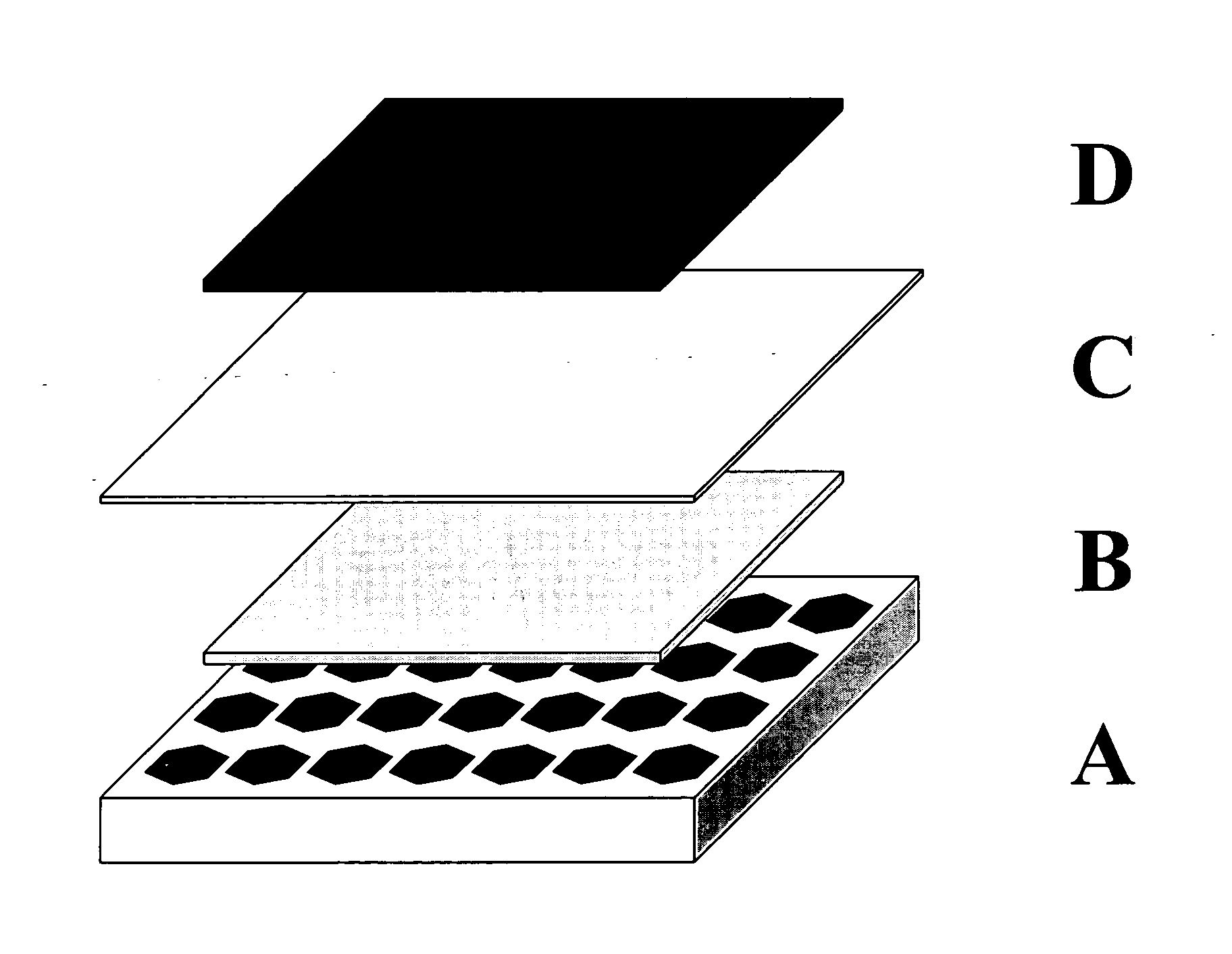
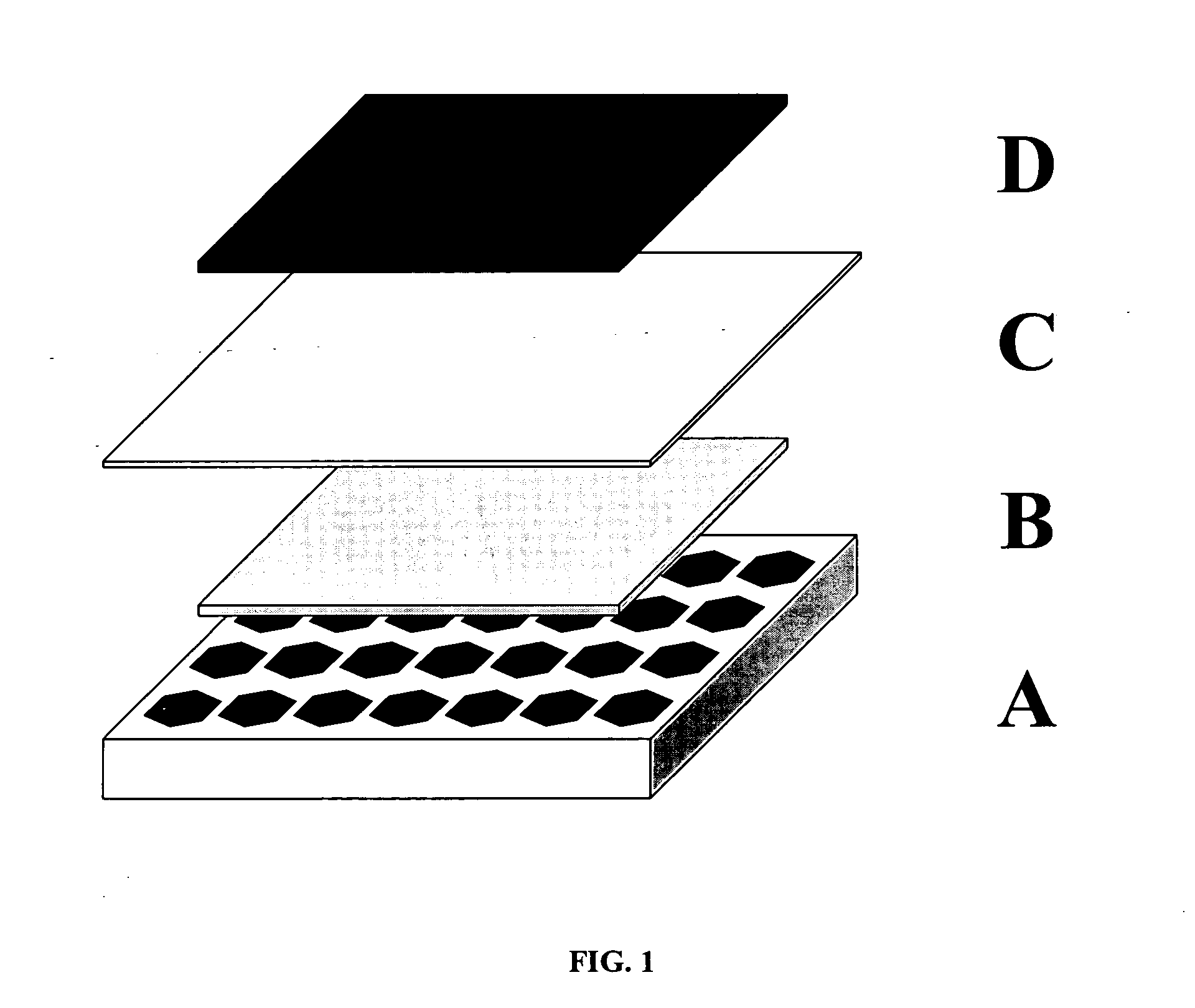
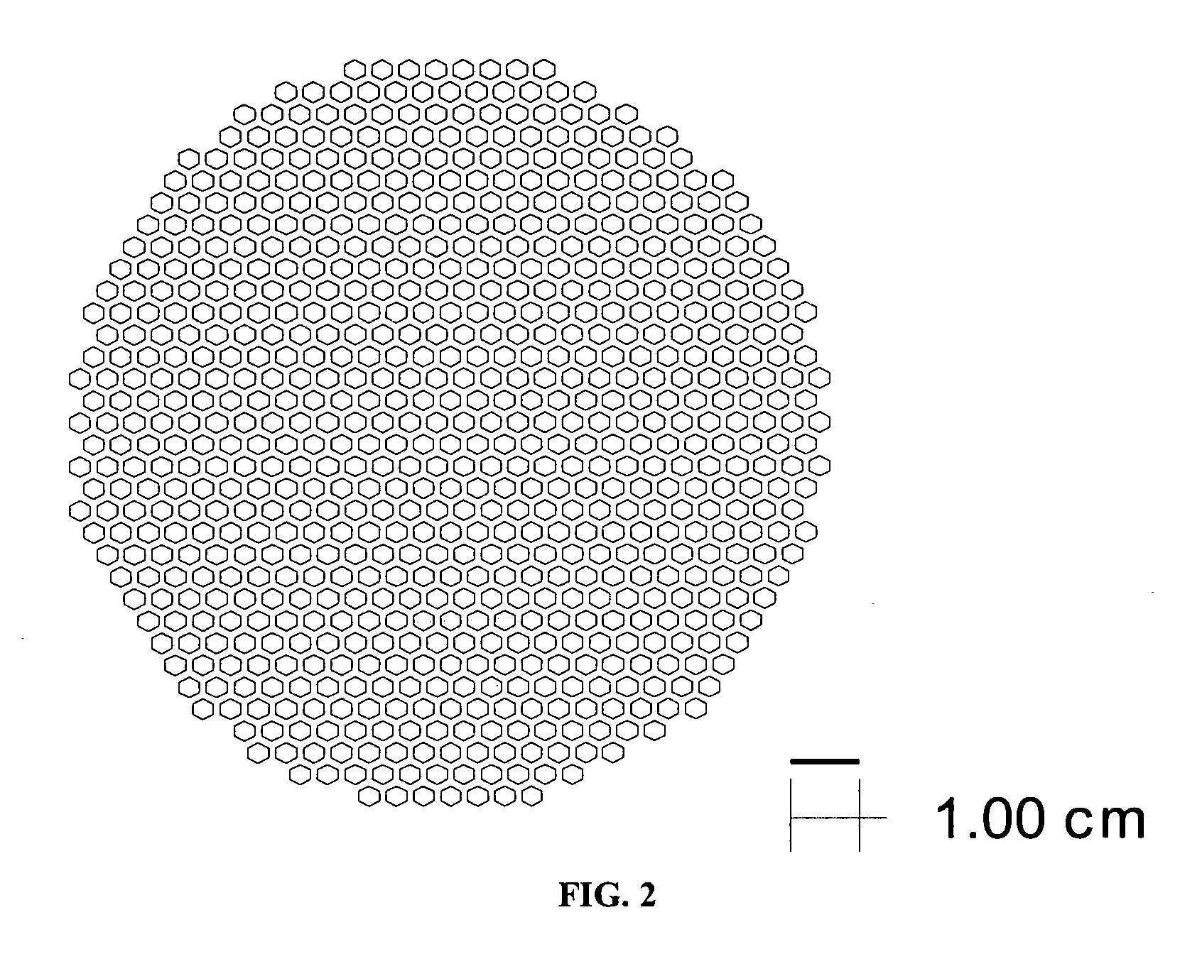
[0070] The tri-layers were constructed with electrolyte and support tapes prepared with 6 mol % scandium-stabilized zirconia powder (initial SSA=8.704 m2 / g). The 6ScSZ tapes for the support structure were prepared by a conventional tape casting method and had a thickness of approximately 45 microns in the green state. The tape was cut into 15×15 cm sheets. The sheets were stacked on top each other, five sheets per stack. The resulting five-sheet stack was laminated at 80° C. and 12 MPa. The pattern shown in FIG. 2 was then cut in the laminate using a laser cutting system. The cut-out laminate was set aside.

[0071] The porous anode layer was constructed with cast tapes prepared with a nickel oxide and yttria-stabilized zirconia powder mixture. This mixture was made using 60 mol % NiO powder (Novamet) and 40 mol % yttria-stabilized zirconia (Unitec). The thickness of the dry tape was 45 microns. The sheets were then cut by hand to 15 cm×15 cm, moved...

example 2

Preparation of Membrane Structure II

[0074] The tri-layers were prepared, cast and laminated as described in Example 1. The support laminate was laser cut to produce the pattern shown in FIG. 6. The cut-out laminate was set aside. The two-sheet electrolyte-electrode stack was prepared as described in Example 1 and laminated with the cut-out support, also as described in Example 1. The final part was cut out of the laminate using the pattern shown by the dashed line in FIG. 7. The resultant component was sintered at 1400° C. for two hours to densify the electrolyte and support layers.

example 3

Preparation of Membrane Structure III

[0075] The tri-layers were prepared, cast and laminated as described in Example 1. The support laminate was laser cut to produce the pattern shown in FIG. 8. The cut-out laminate was set aside. The two-sheet electrolyte-electrode stack was prepared as described in Example 1 and laminated with the cut-out support, also as described in Example 1. The final part was cut out of the laminate using the pattern shown by the dashed line in FIG. 9. The resultant component was sintered at 1400° C. for two hours to densify the electrolyte and support layers.


PUM

PropertyMeasurementUnit
diameteraaaaaaaaaa
thicknessaaaaaaaaaa
temperaturesaaaaaaaaaa

Abstract

Ceramic membranes with integral seals and support, and related electrochemical cells and cell stacks. The membrane comprises a thin electrolyte layer supported on a porous electrode layer which in turn is supported on a thick ceramic support layer, preferably a ceramic electrolyte support. The support layer is divided into a plurality of self-supporting thin membrane regions by a network of thicker integrated support ribs. The thin electrolyte layer and thick ceramic support layer preferably define a sealing perimeter surrounding the porous electrode layer.

Description

CROSS-REFERENCE TO RELATED APPLICATIONS [0001] Not applicable STATEMENT REGARDING FEDERALLY SPONSORED RESEARCH [0002] Not applicable REFERENCE TO MICROFICHE APPENDIX [0003] Not applicable FIELD OF THE INVENTION [0004] The invention relates to thin film membranes of ceramic materials with integral seals and support, electrochemical cells including these membranes, and stacks formed from these electrochemical cells. The disclosed membrane and resultant cell and stack architecture are particularly well suited to applications in which mechanical ruggedness and volumetric and gravimetric reaction density are desirable. This invention may be useful in electrochemical separations and catalytic reactors including but not limited to solid oxide fuel cells and oxygen separation membranes. BACKGROUND OF THE INVENTION [0005] Tubular solid oxide fuel cells (SOFCs) are the most extensively demonstrated of the many designs proposed for SOFCs. In these structures, a multi-layer tube is fabricated w...

Claims


Application Information

Patent Timeline
Patent Type & Authority Applications(United States)
IPC IPC(8): H01M8/12H01M8/02H01M8/24
CPCH01M4/9033H01M8/0282H01M8/1226Y02E60/525H01M2008/1293H01M2300/0074Y02E60/521H01M8/2435Y02E60/50H01M8/02H01M8/12H01M8/24
Inventor DAY, MICHAEL J.FUNK, J. MICHAELLESOUSKY, TODD G.SEABAUGH, MATTHEW M.
Owner NEXCERIS INNOVATION HLDG LLC
Why Eureka
Try Eureka